Instructions are in beta
If you have any issues or feedback for these instructions, do not hesitate to contact me via email at hello at lifeclo.cc
If you have any issues or feedback for these instructions, do not hesitate to contact me via email at hello at lifeclo.cc
You should know how to solder. This project is perfectly doable with just a soldering iron and solder, but knowing how to use solder flux and a desoldering wick will definitely make your life easier.
| Part | Count | PCB Label | Image |
|---|---|---|---|
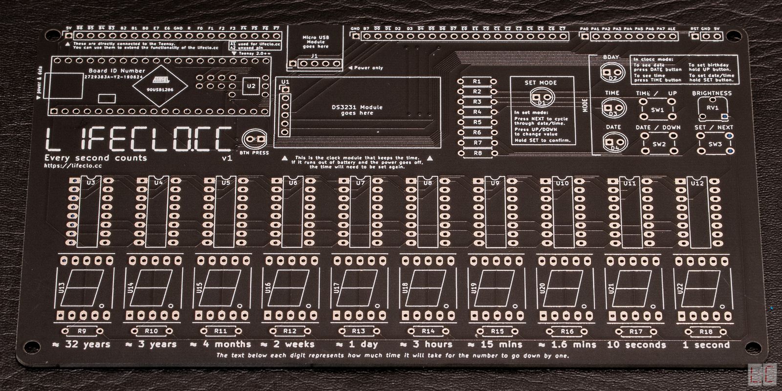
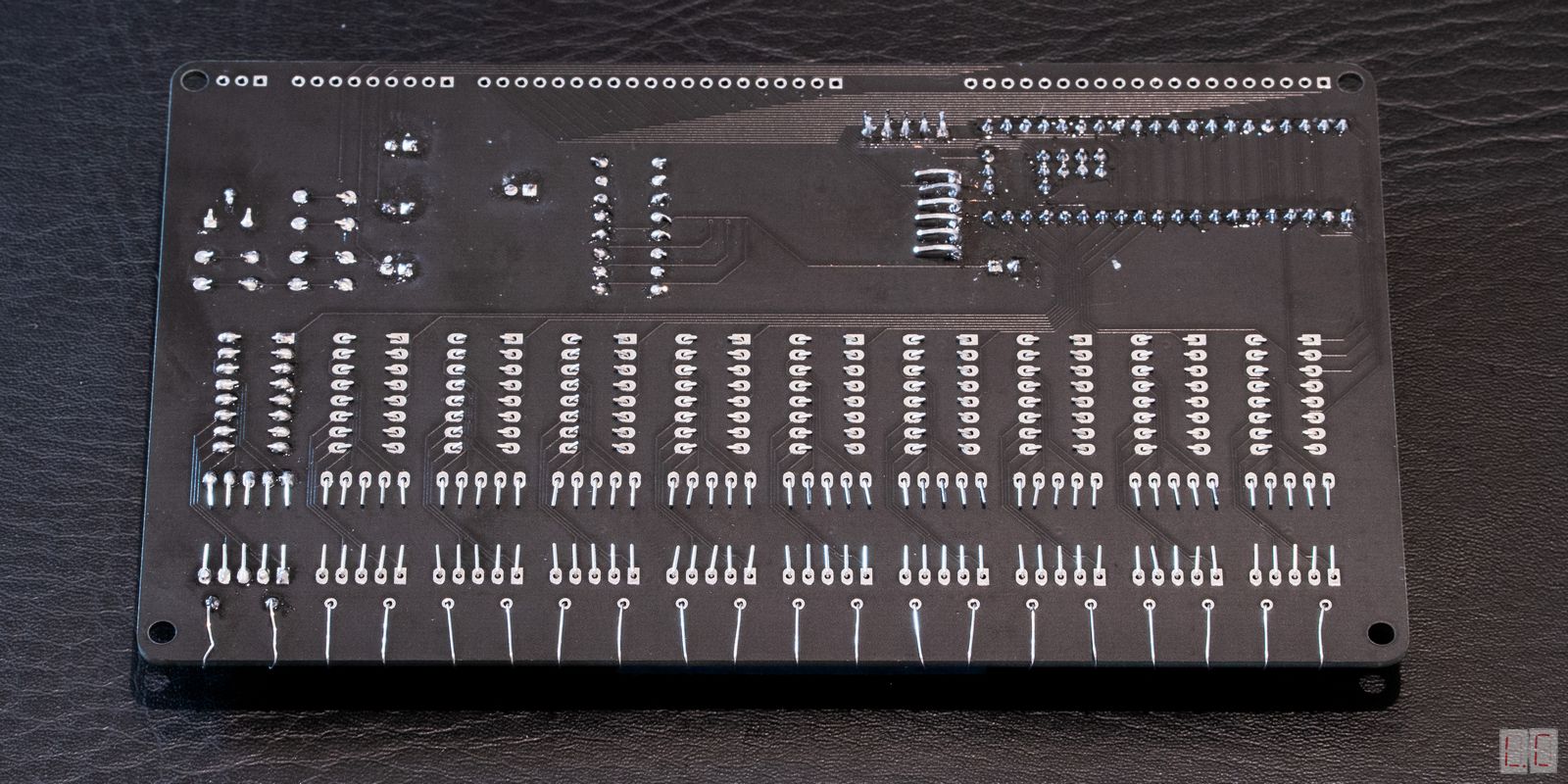
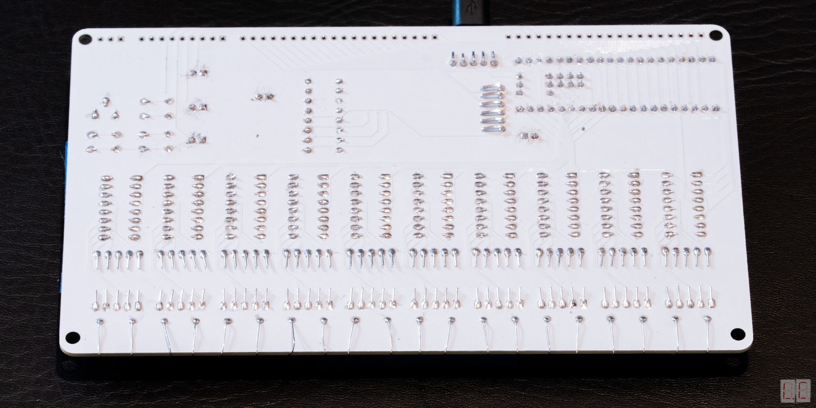
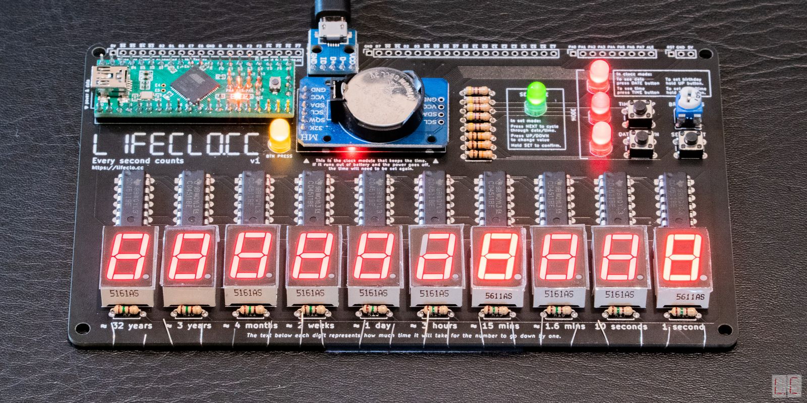
| Printed Circuit Board (PCB) | 1 | - | |
|
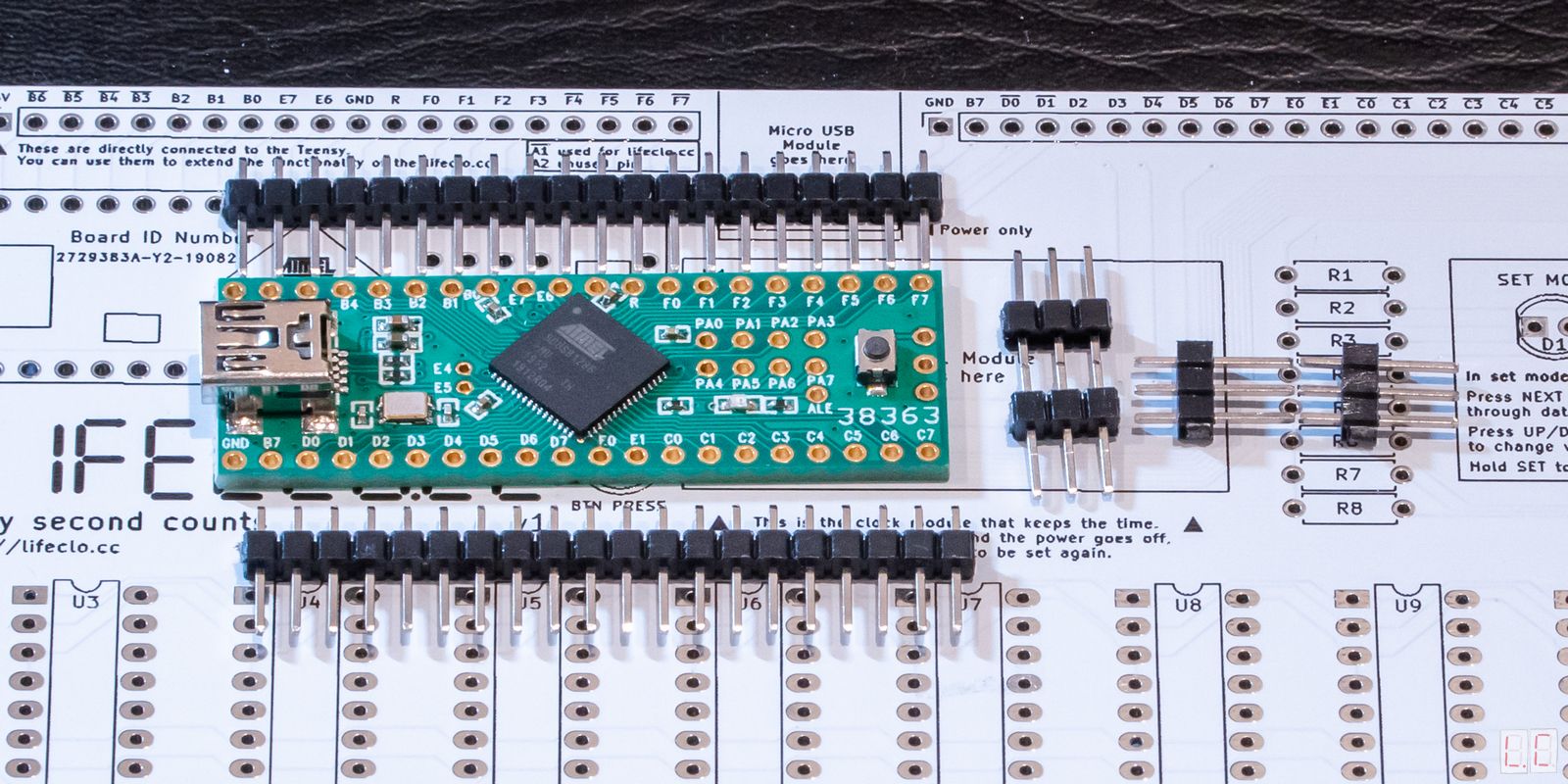
Teensy 2.0++ with Header Pins |
1 | U2 | |
|
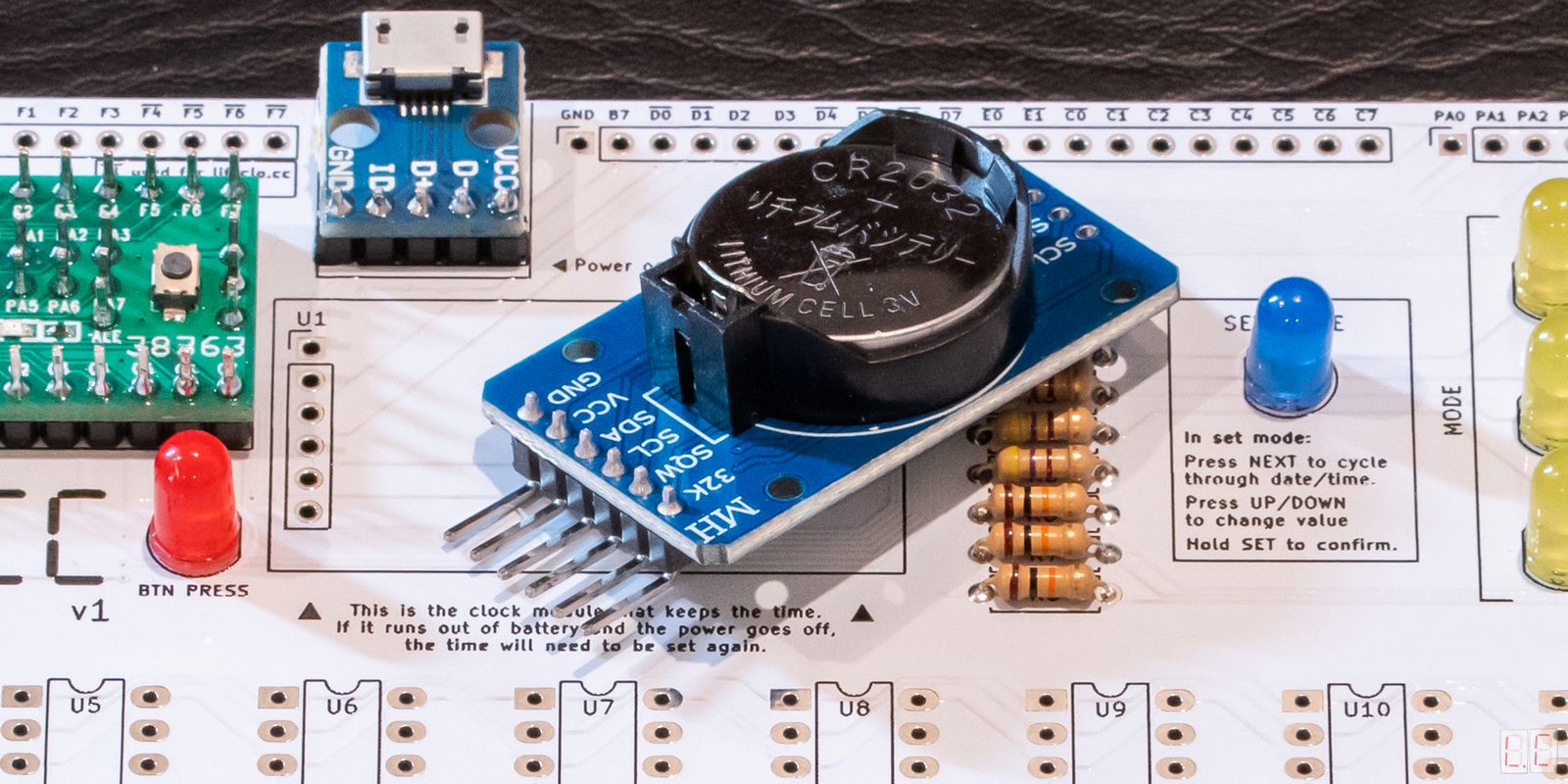
DS3231 Module with CR2032 Button Battery |
1 | U1 | |
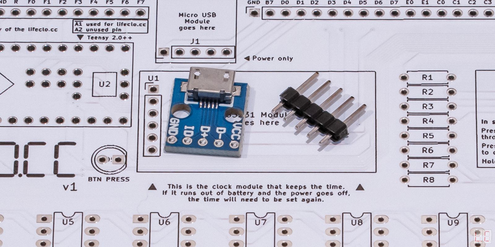
| Micro USB Module | 1 | J1 | |
|
SET LED Colours may vary |
1 | D1 | |
|
BDAY/TIME/DATE LED Colours may vary |
3 | D2 D3 D4 | |
|
BTN LED Colours may vary |
1 | D5 | |
| Tactile Buttons | 3 | SW1 SW2 SW3 | |
|
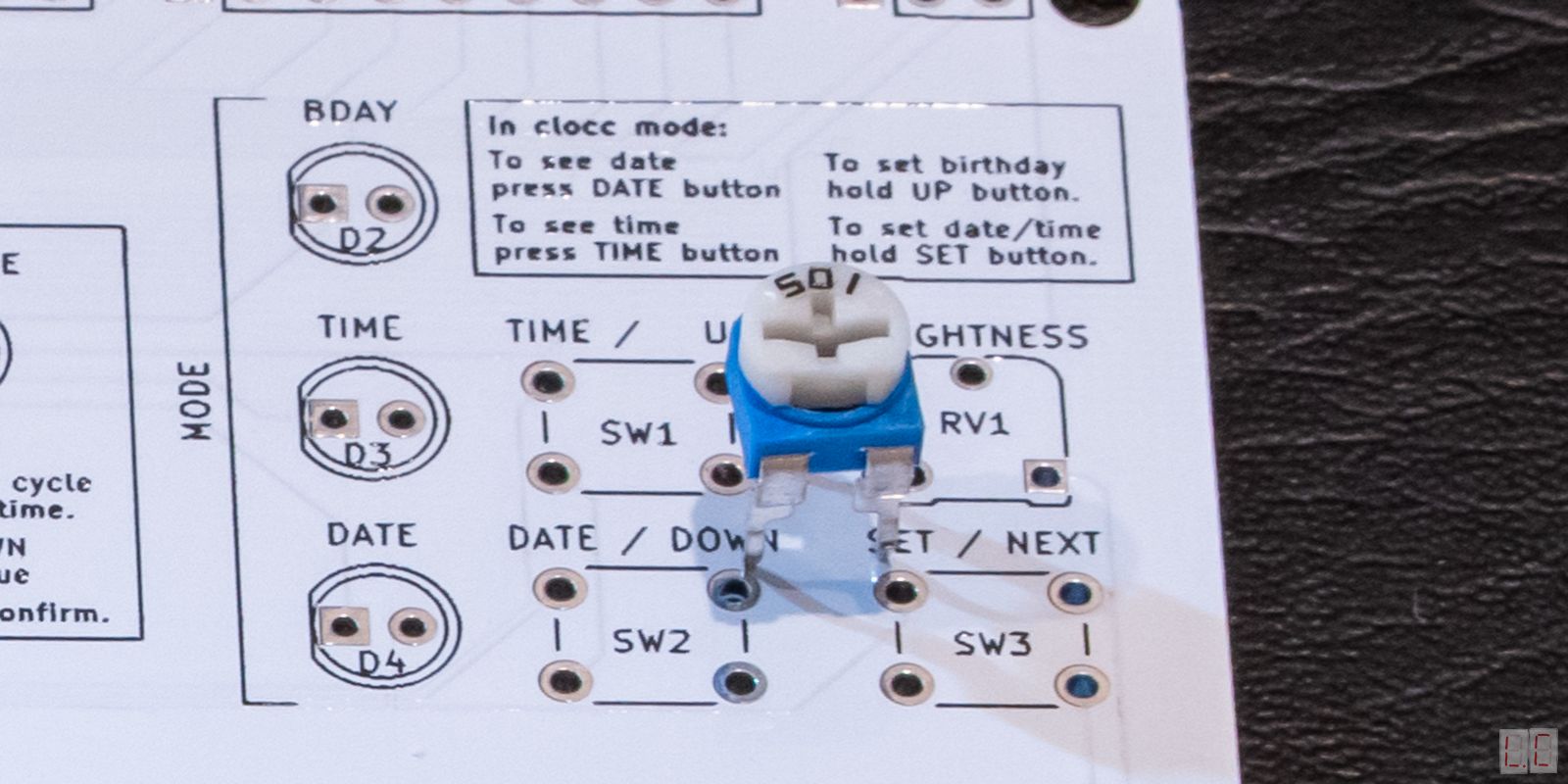
500Ω Variable Resistor Label 501 |
1 | RV1 | |
|
4511 DIP-16 IC BCD to 7-segment decoder |
10 | U3 U4 U5 U6 U7 U8 U9 U10 U11 U12 | |
|
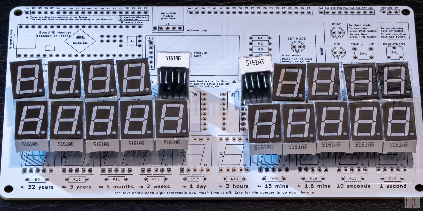
7-segment display Common Cathode 5161AG = Green Display 5161AS = Red Display |
10 | U13 U14 U15 U16 U17 U18 U19 U20 U21 U22 | |
|
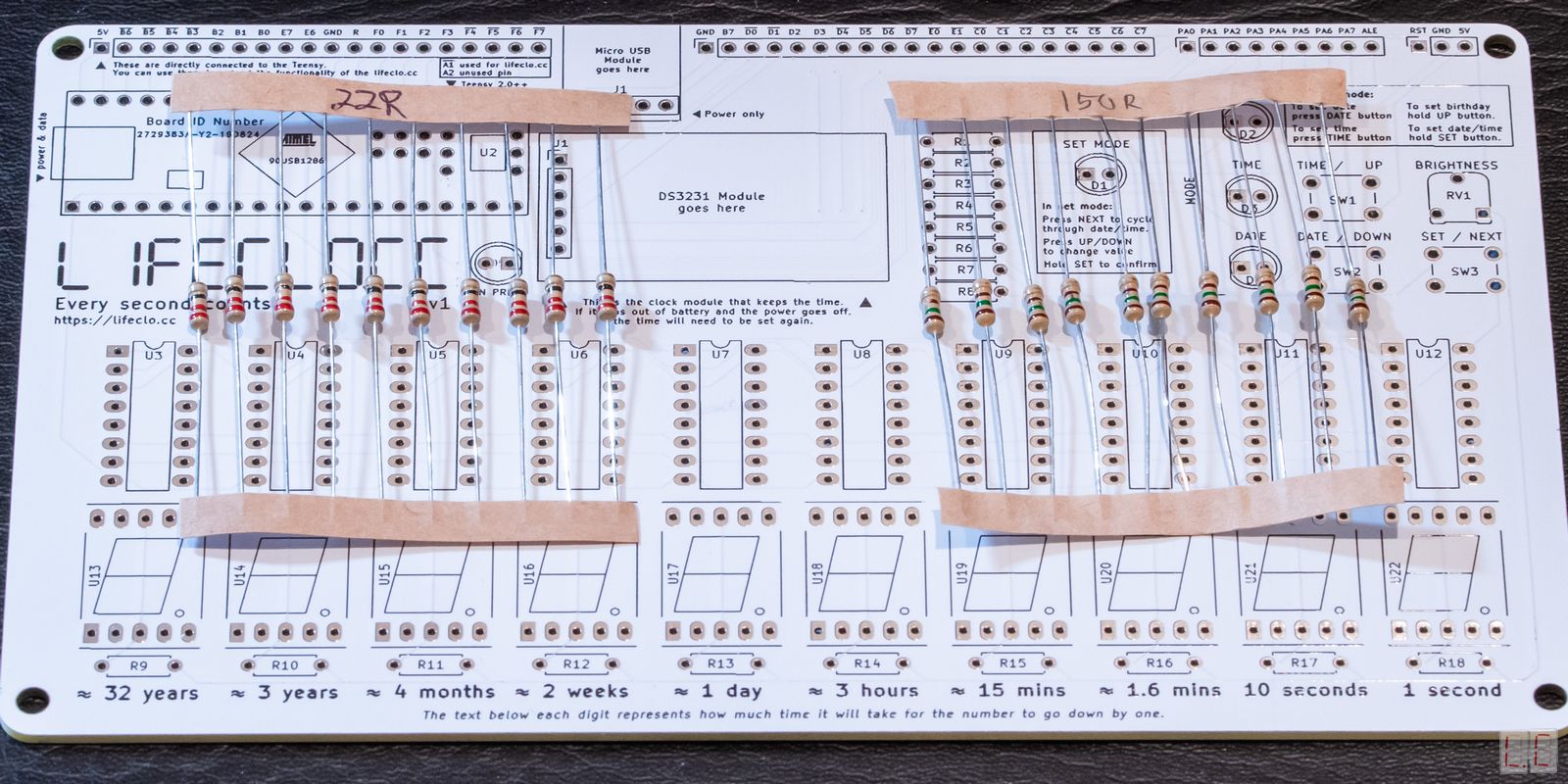
22Ω / 150Ω Resistor
22Ω for
Green
Display |
10 | R9 R10 R11 R12 R13 R14 R15 R16 R17 R18 | |
|
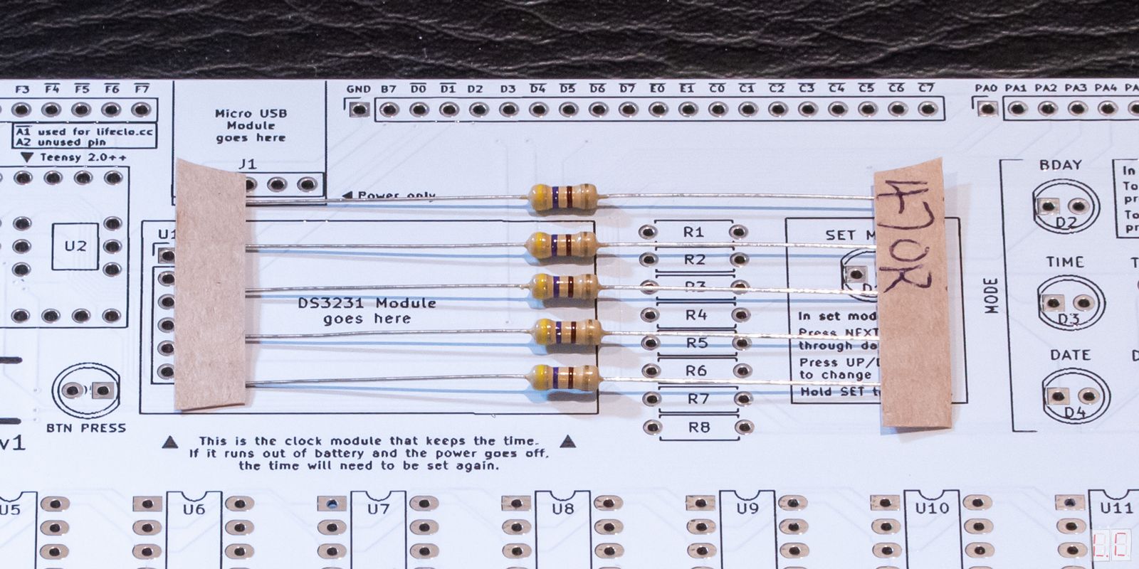
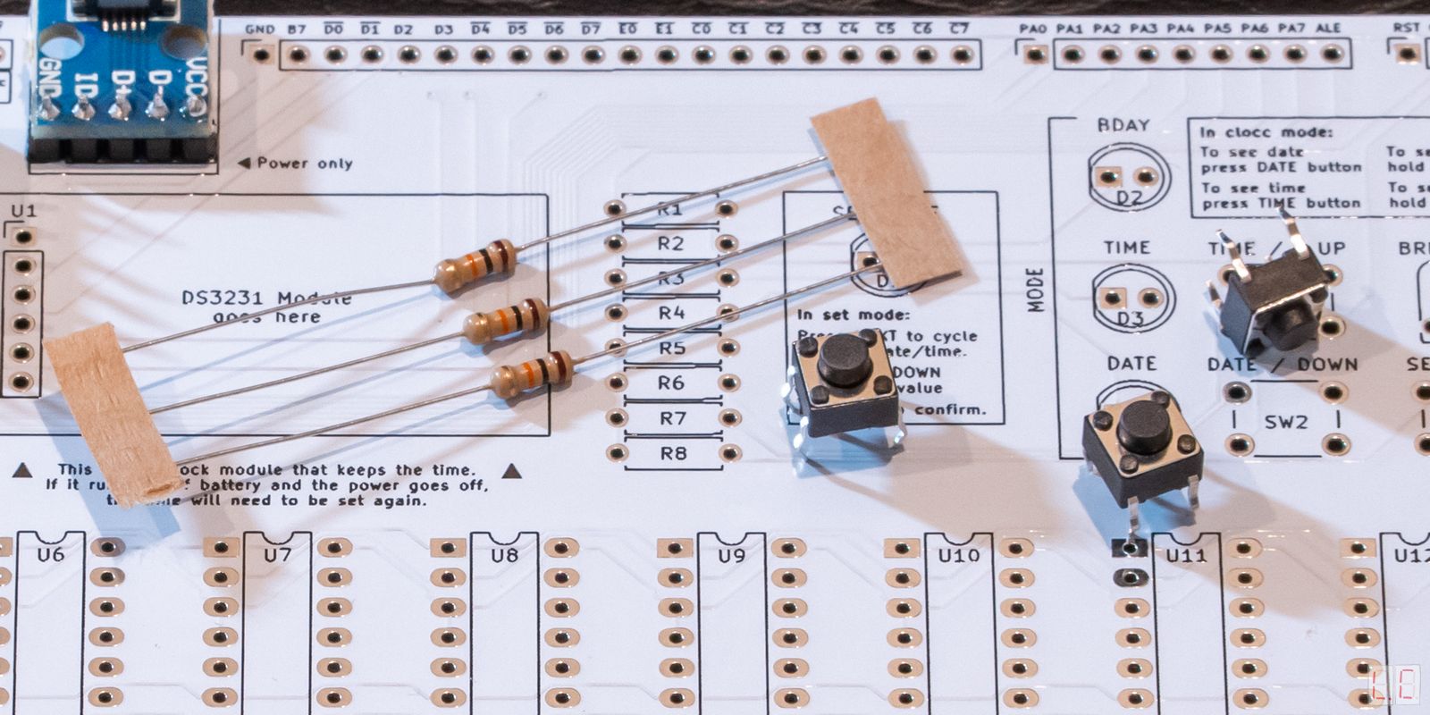
470Ω Resistor |
5 | R1 R2 R3 R4 R5 | |
|
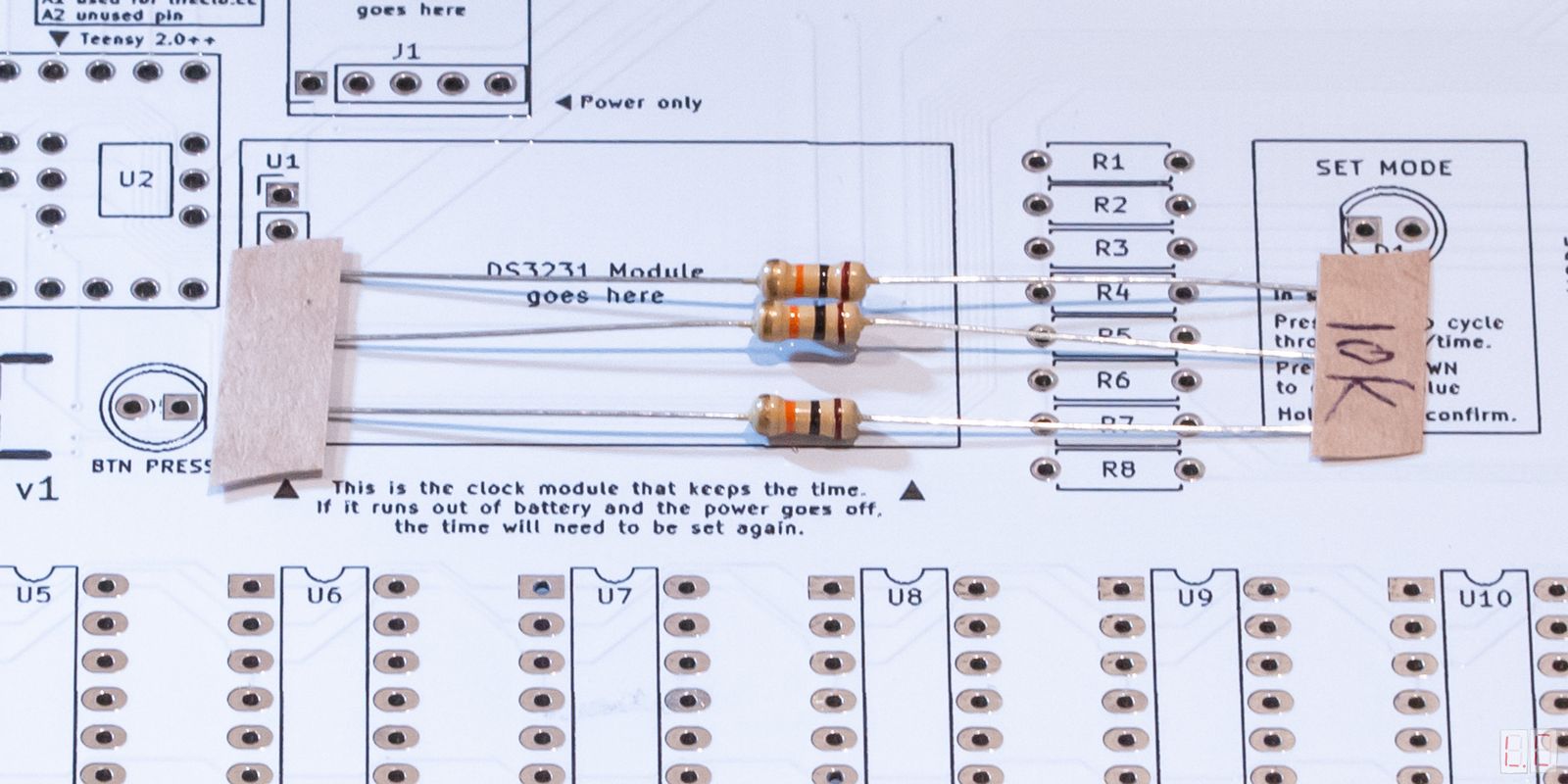
10kΩ Resistor |
3 | R6 R7 R8 | |
|
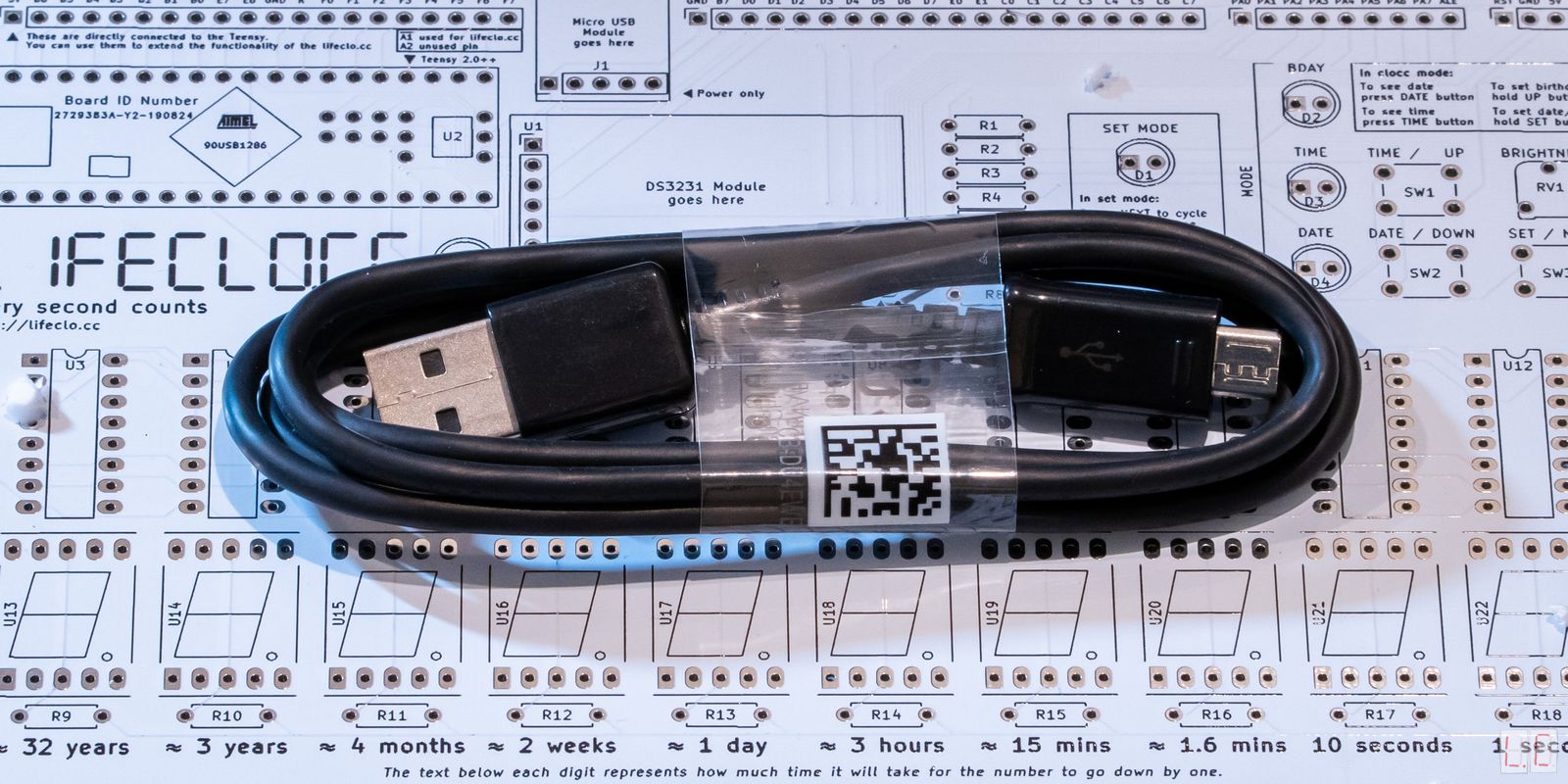
Micro USB Wire Used for power only, to program it you need a mini USB wire. |
1 | - |
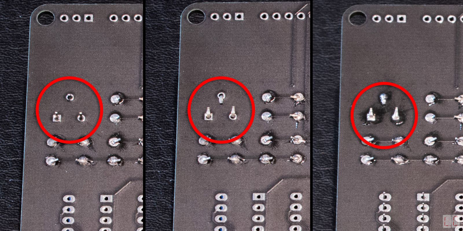
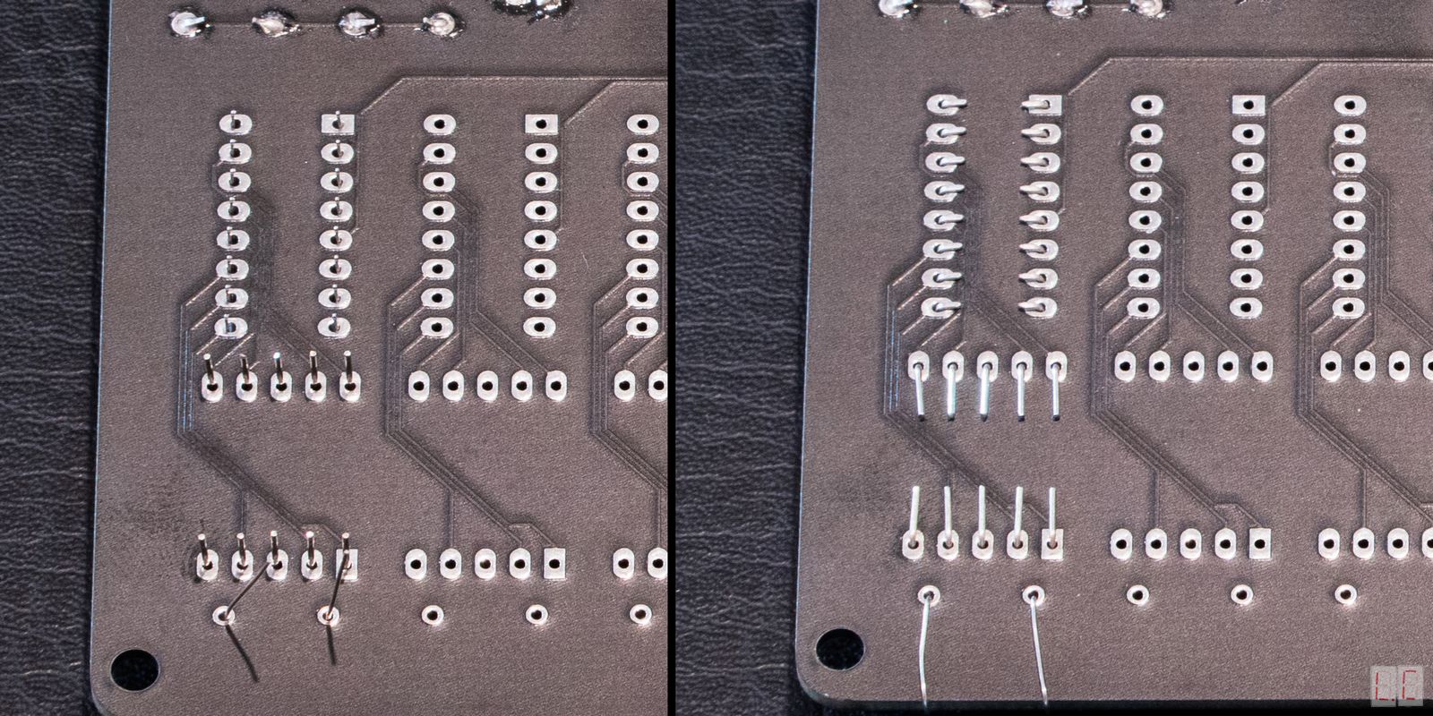
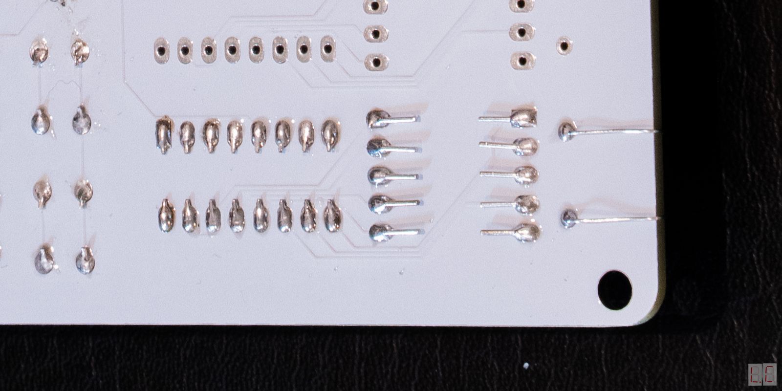
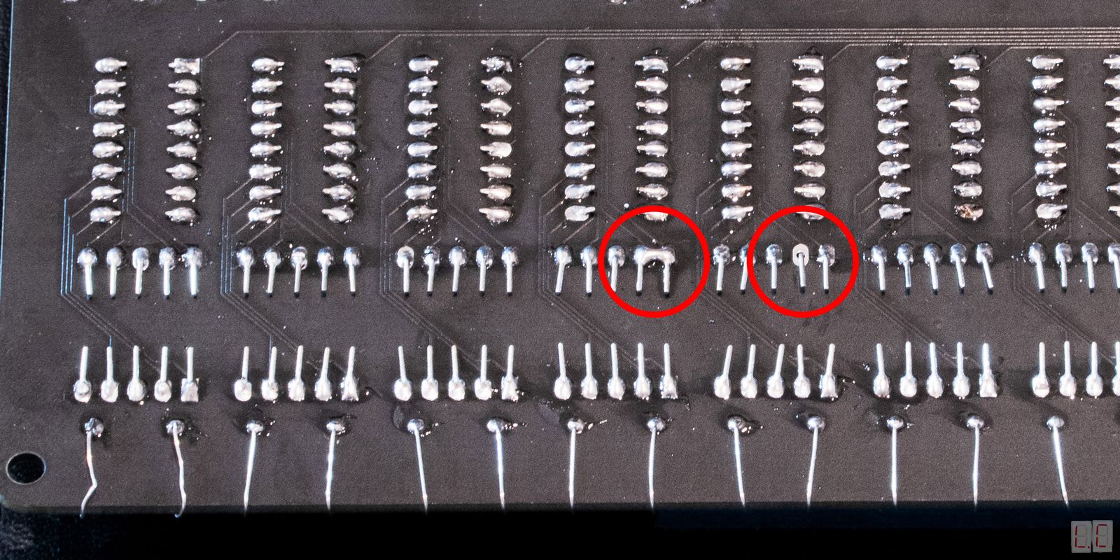
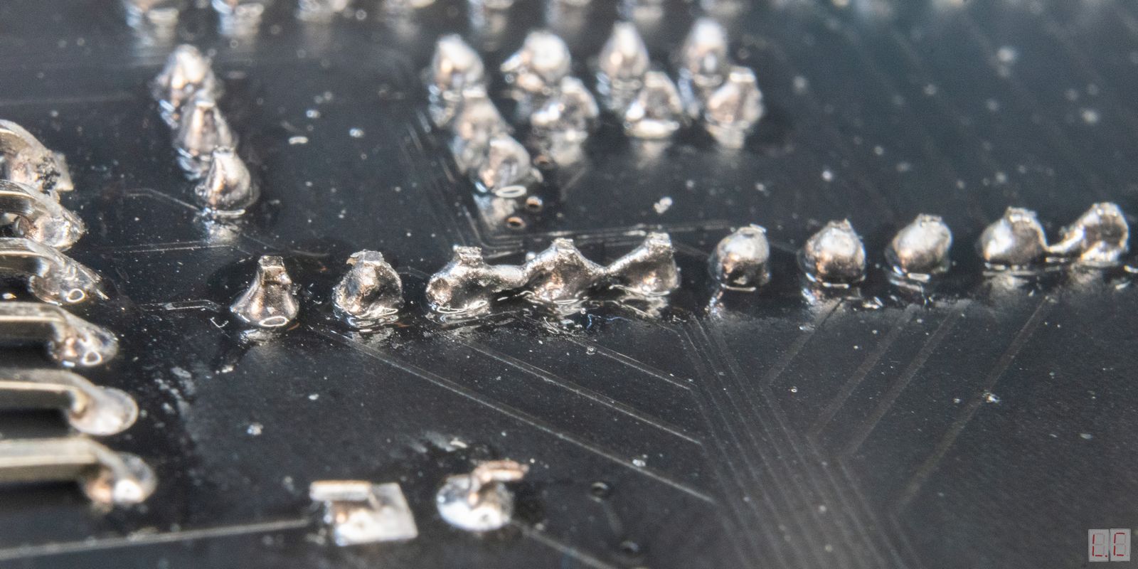
Always check the direction of the componets before soldering it. If you have mistakenly soldered an IC upside down, it is very difficult to remove and redo it. In the event that happens, you will likely need a solder wick and a lot of patience.
For soldering any component, it’s best to solder only one pin first and then check if it’s aligned. If it’s not aligned, you will be able to melt the solder and reposition the component/ After that, solder the second pin that’s diagonally across. By doing this, you can be sure that the component is positioned correctly before soldering the rest of the pins.
For all components, you can choose to use Male to Female header pins instead of soldering them directly to the board. This means that you can easily remove and replace components if necessary.
This video tutorial runs through the same steps as the instructions below. Just that it's in video form.
Plug the Teensy into any USB port with the provided Mini USB cable.
The onboard LED should flash 4 times. This indicates that the device is running properly.
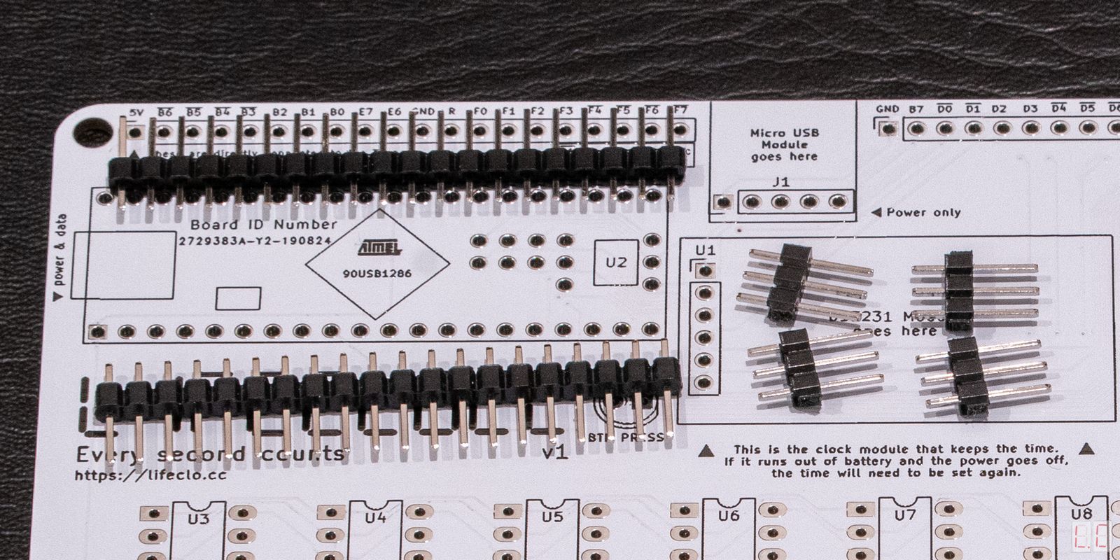
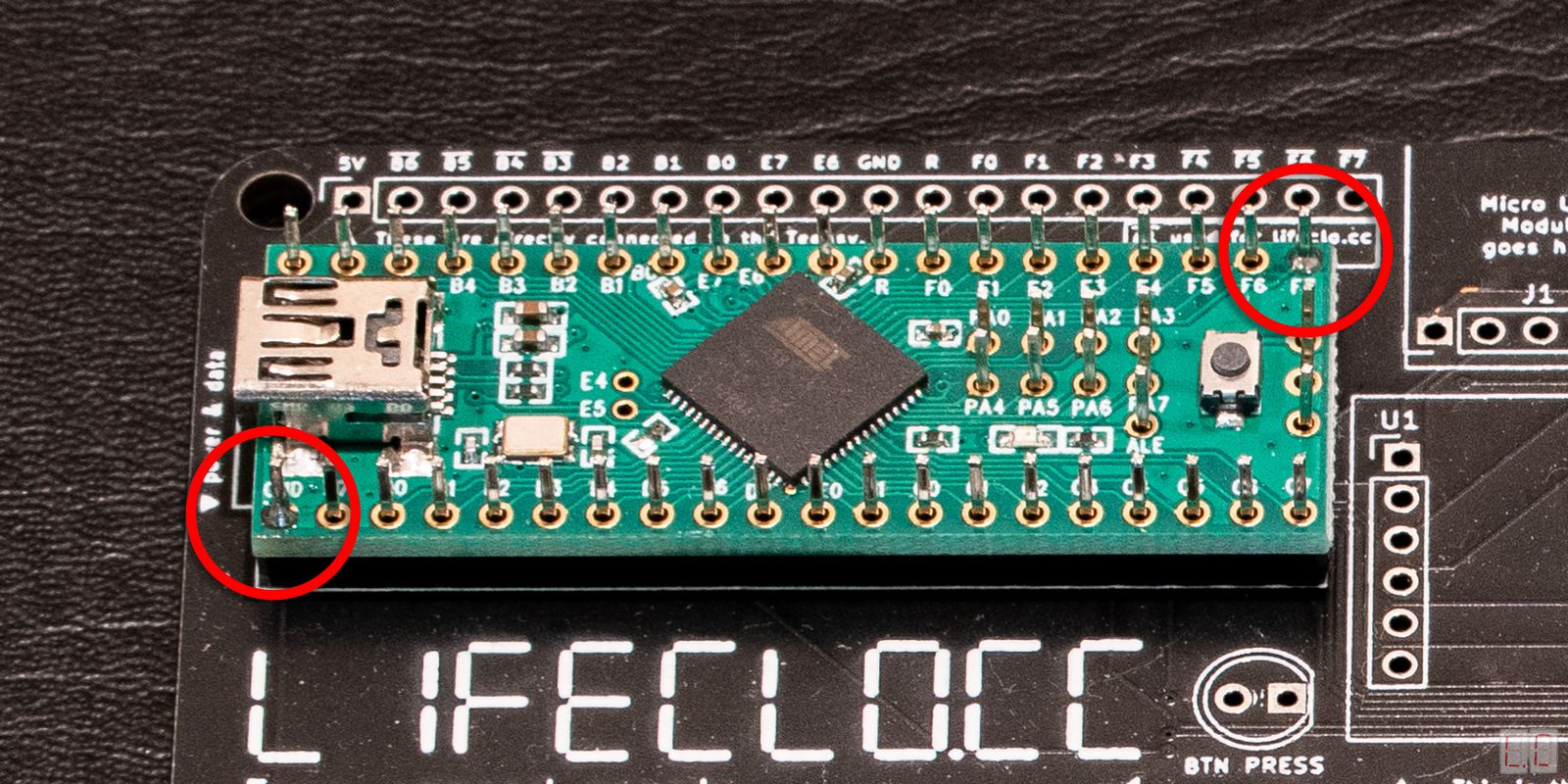
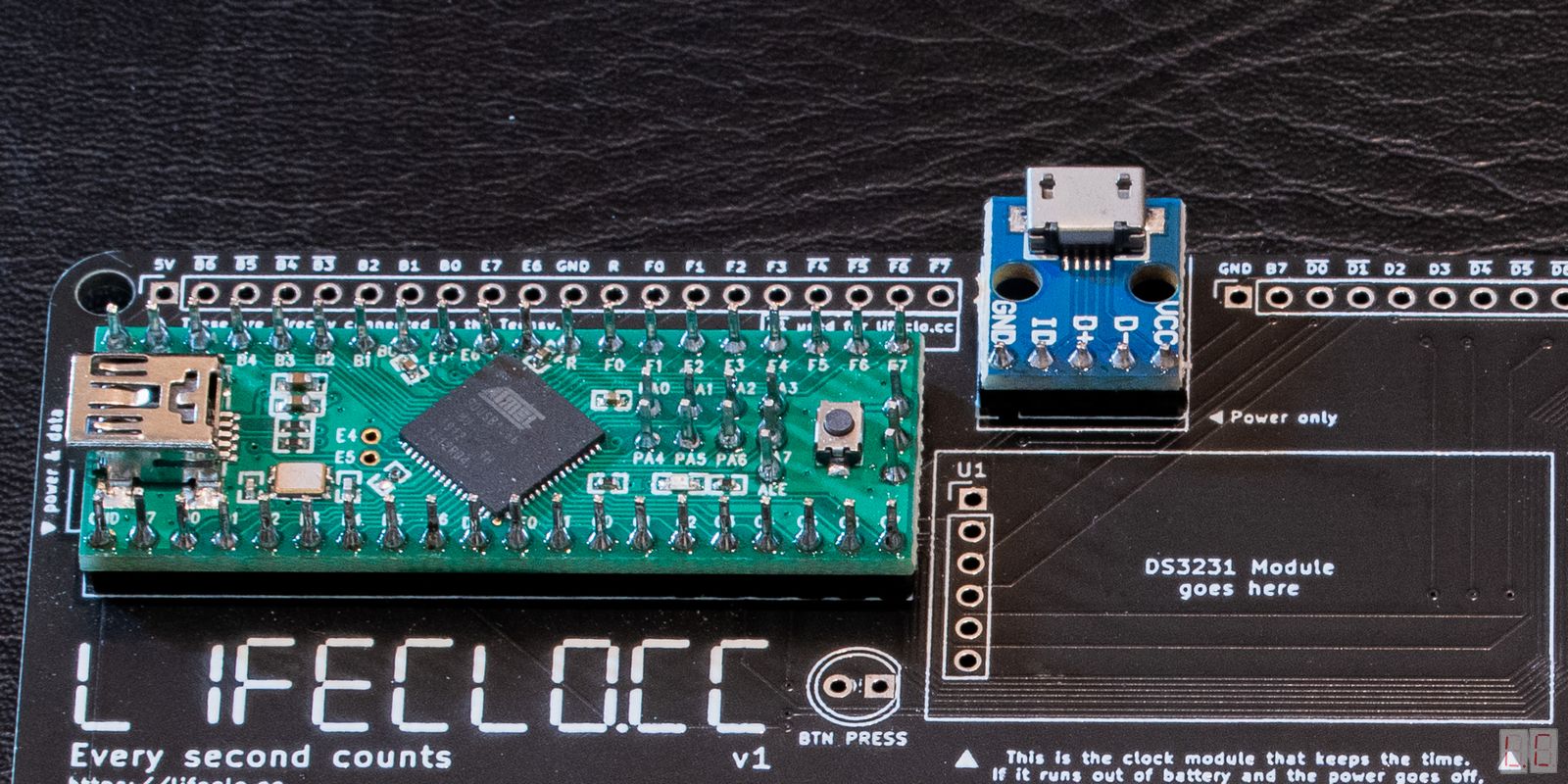
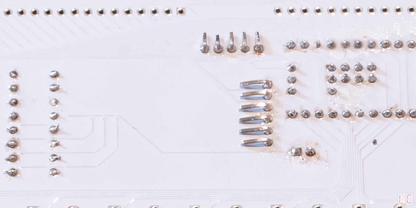
The Teensy will come with all the header pins separate from the board. You will need to solder the header pins to the board and to the Teensy.
The Teensy Microcontroller has small resistors and other components on board. When soldering, take care not to desolder or short circuit anything on the board.
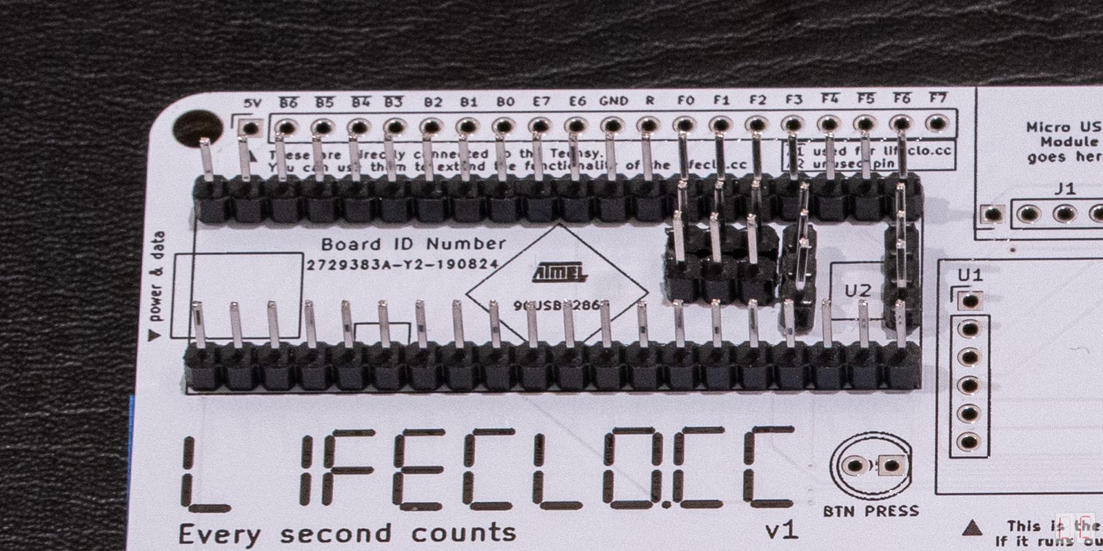
This part is slightly tricky, because if you don’t align the pins properly, you won’t be able to fit them into the board later on. The trick is to place all the pins into the PCB, then place the Teensy in without soldering anything.
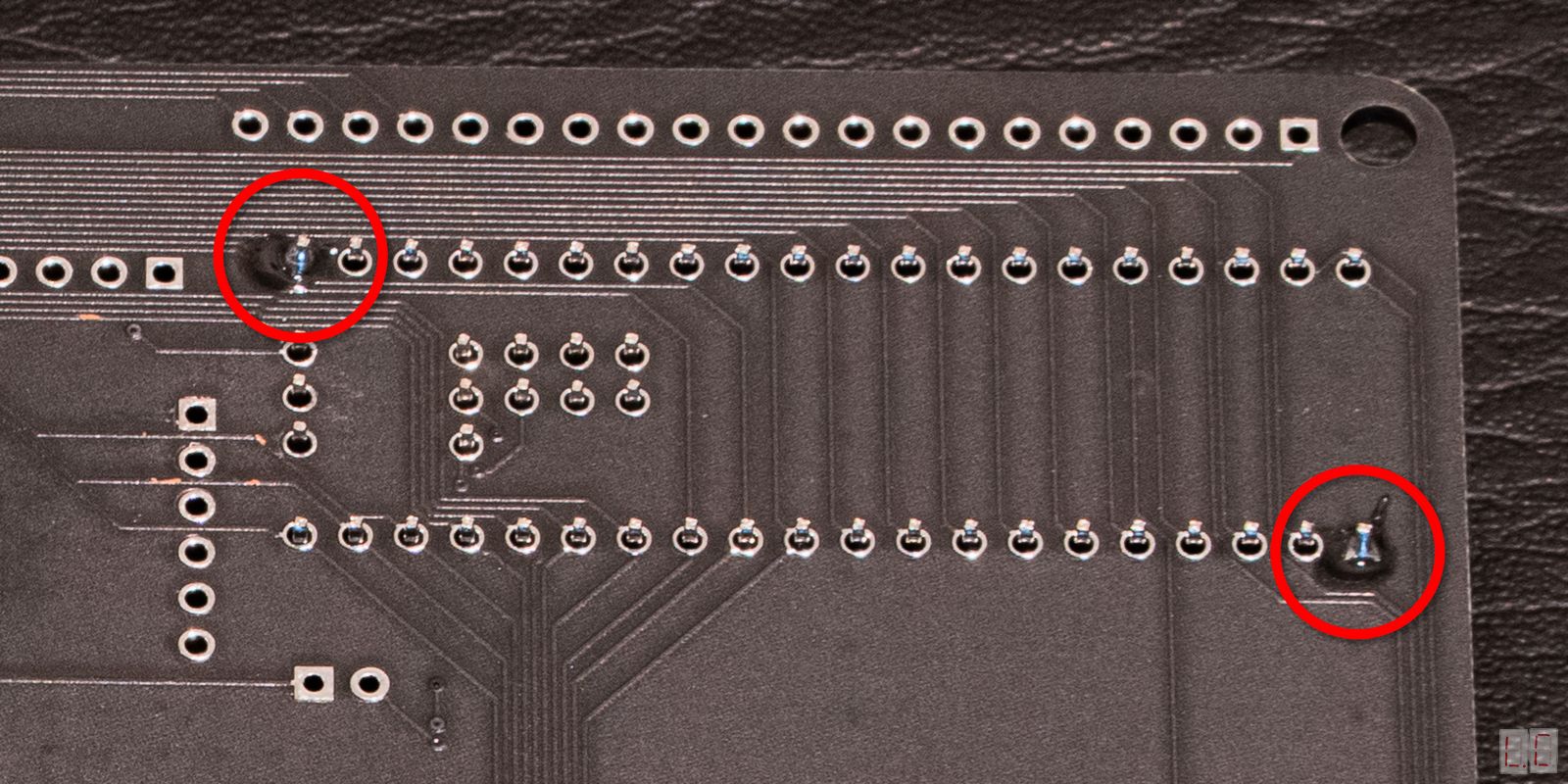
After that, solder the two corners of the Teensy and the two corners on the PCB. The reason we do this is that if we make any mistake, we can easily heat up the pins and readjust them.
With that, the rest of the pins will be held in place and you can take your time to solder the rest without worrying that the pins will fall out.
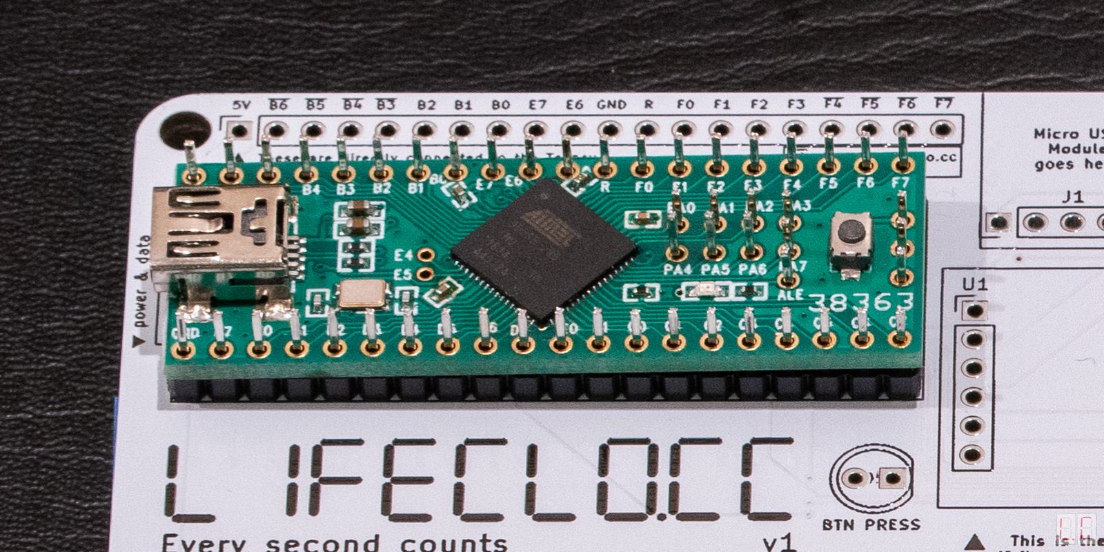
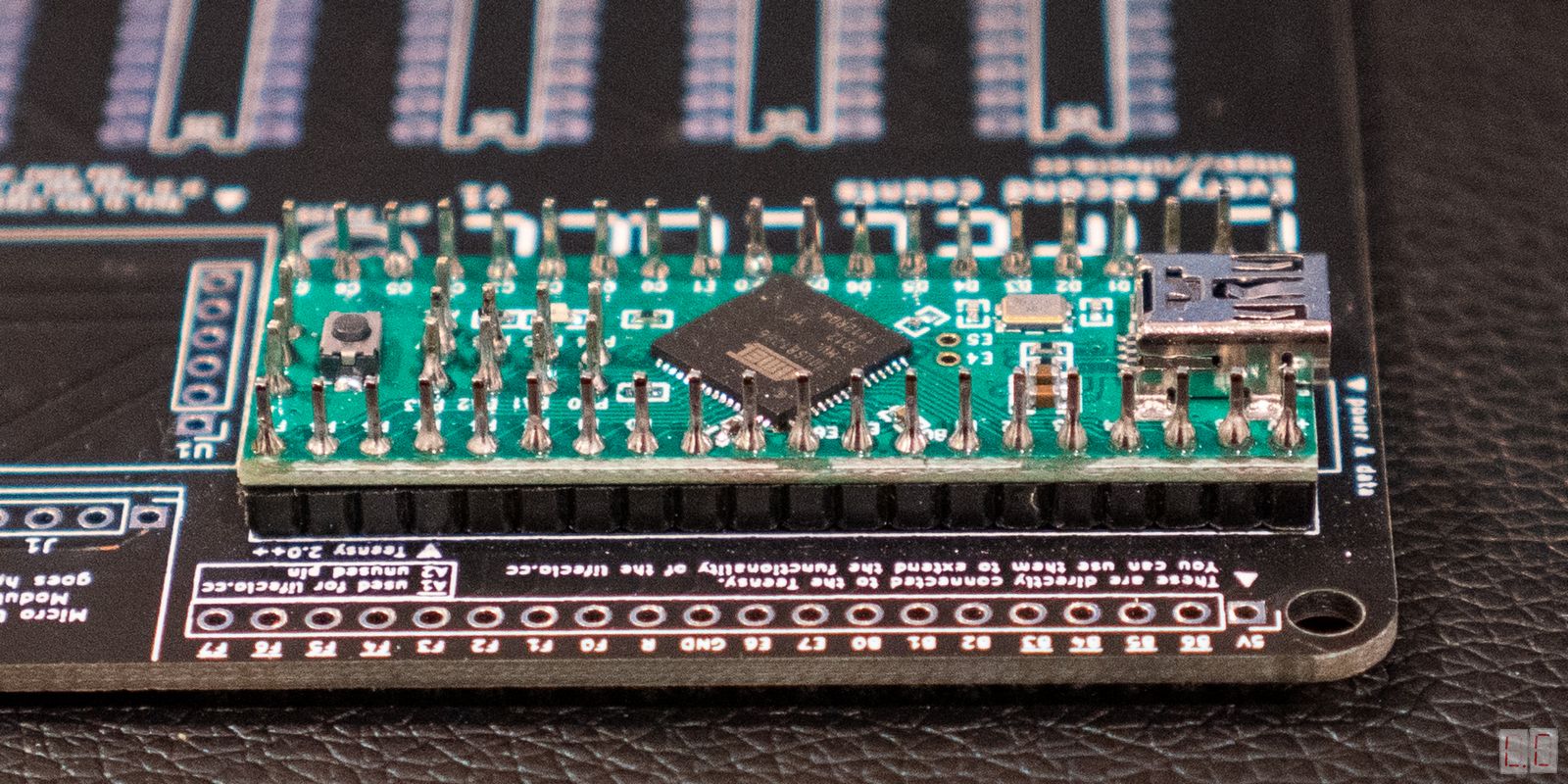
Plug in the Teensy to make sure that it's still working
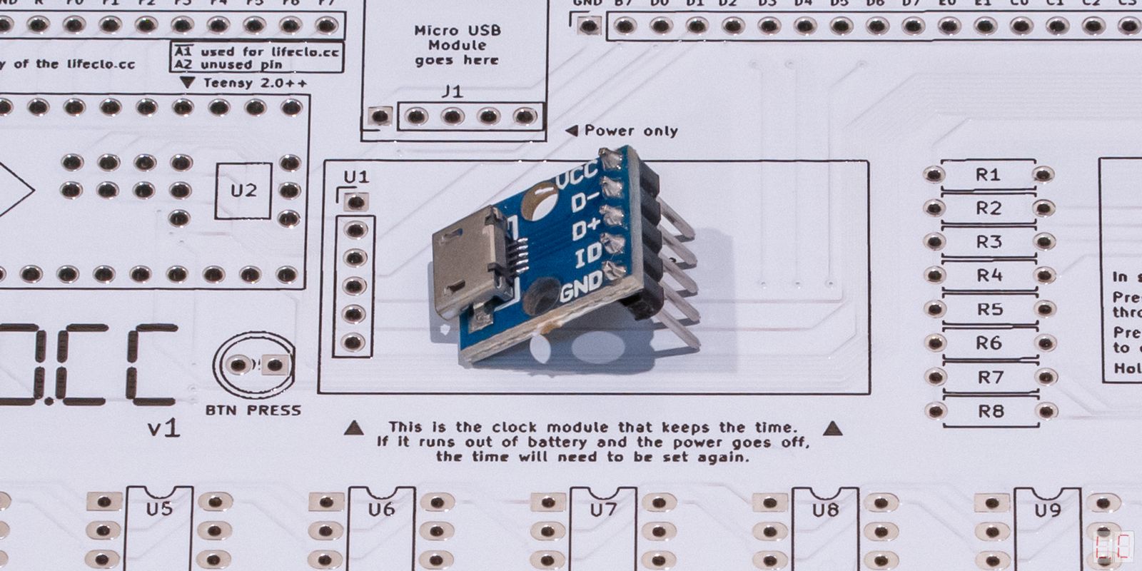
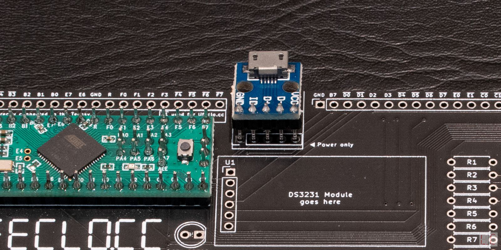
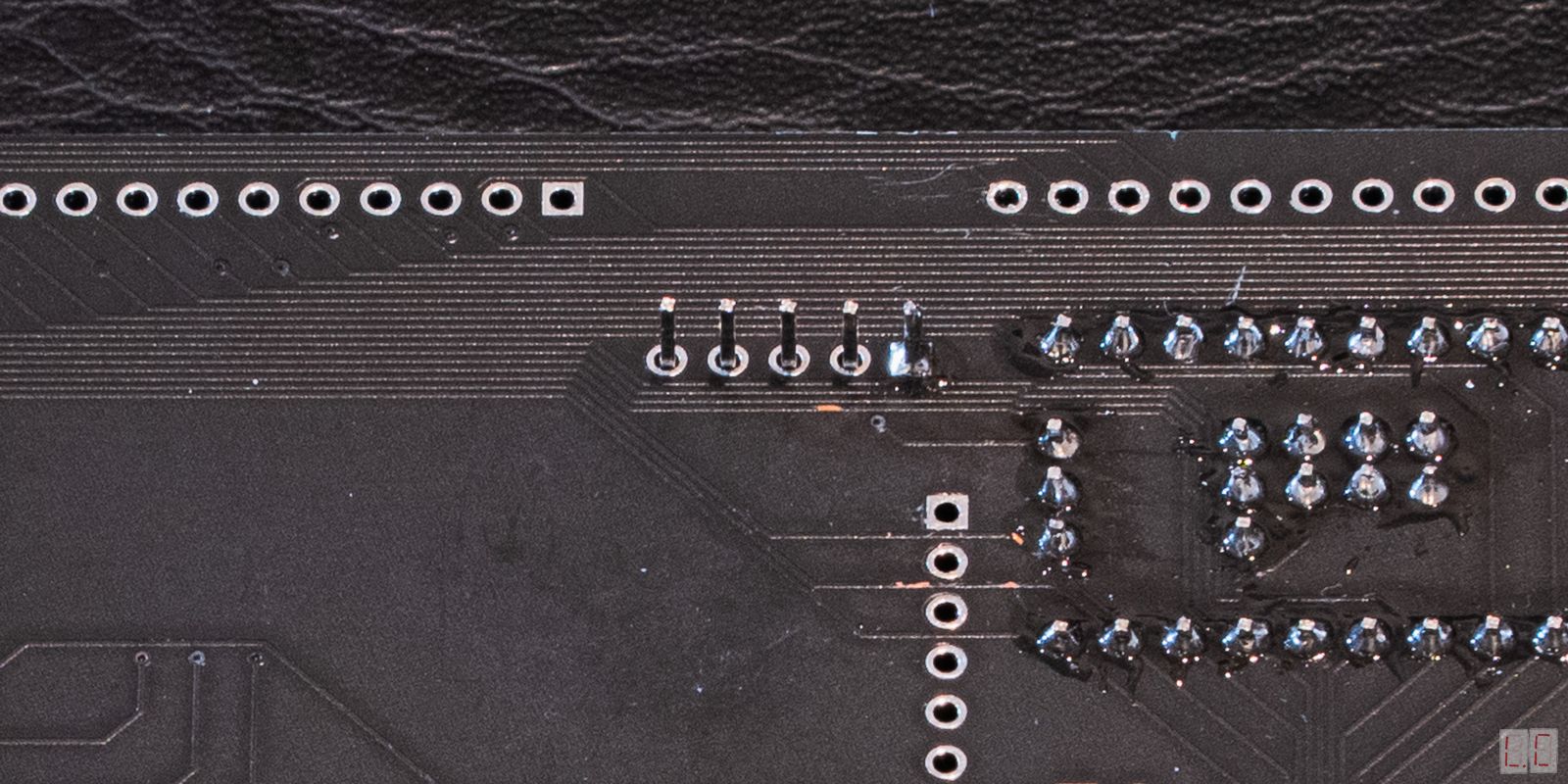
Solder the header pins onto the Micro USB breakout first.
After that, fit the breakout board into the area labelled Micro USB Module, and solder a single pin. This will allow you to align the board before committing to all of them.
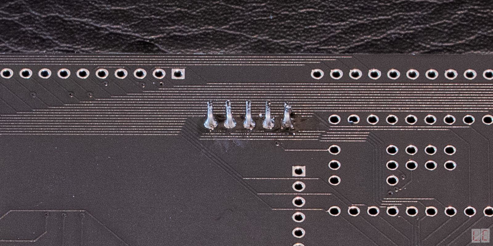
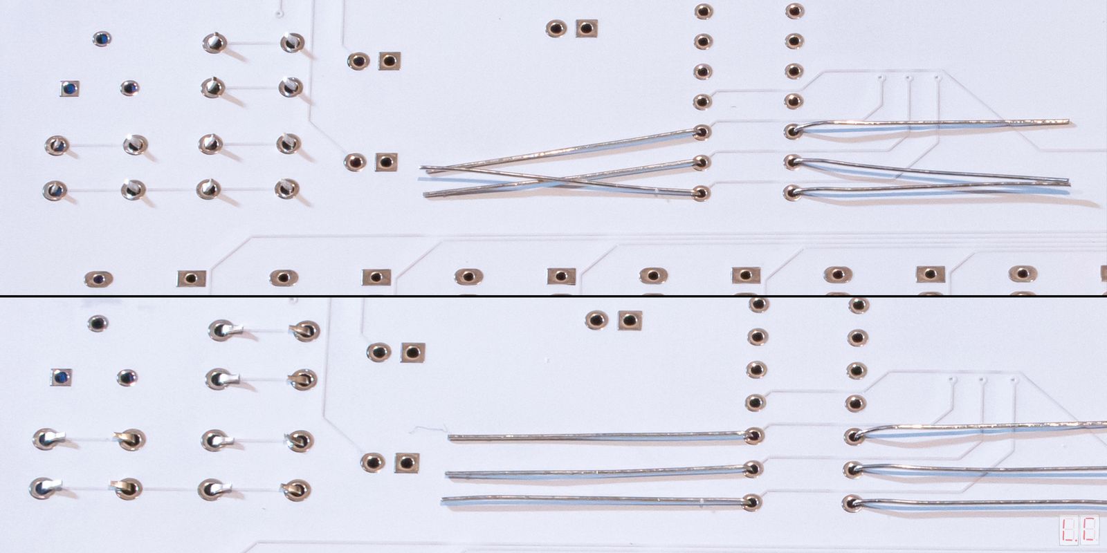
After you have soldered all the legs to the PCB, you can bend the legs or cut them off.
This breakout only provides power to the board and does not allow you to program the Teensy. If you want to program it, please refer to the programming section.
Plug the micro USB cable in. The Teensy should light up and blink 3 times.
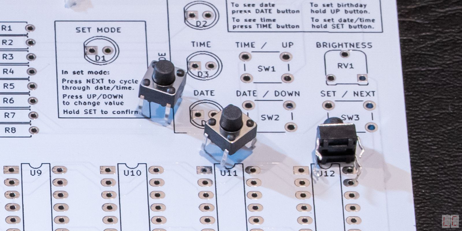
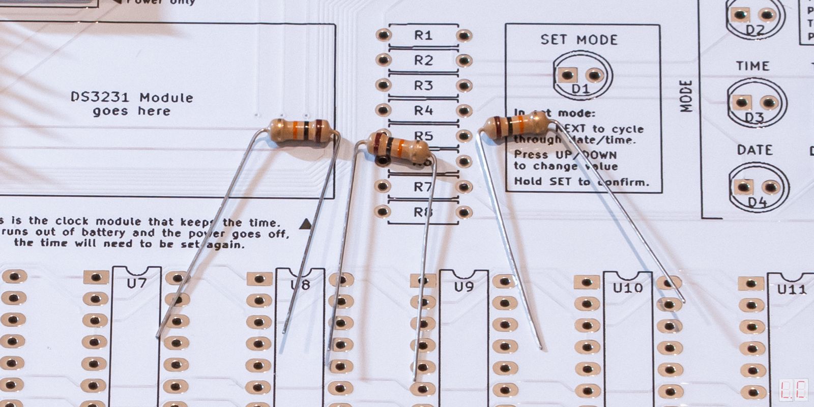
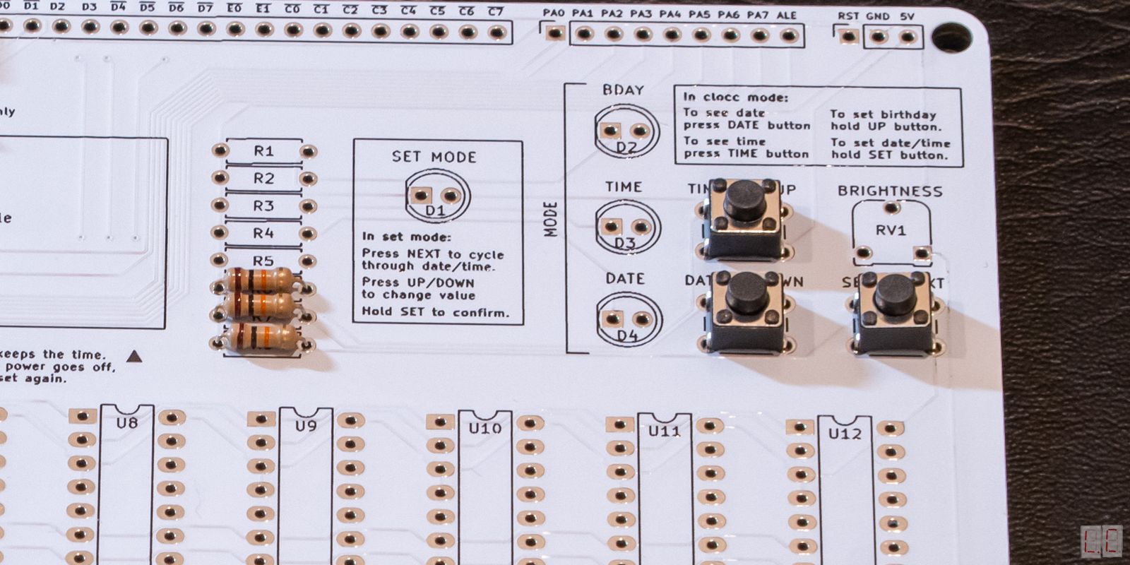
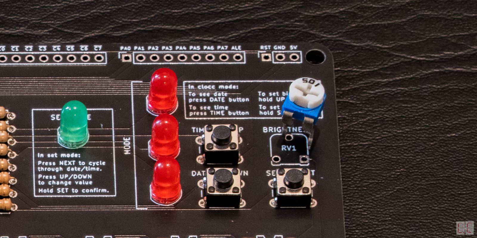
You will need to solder the buttons into SW1, SW2, and SW3, and the 10KΩ Resistors into R6, R7, R8. The directions of these components do not matter.
Plug the Teensy in
When you press the buttons, the LED on board the Teensy
should light up to indicate that it detects the button
presses.
Unplug the device before continuing to solder.
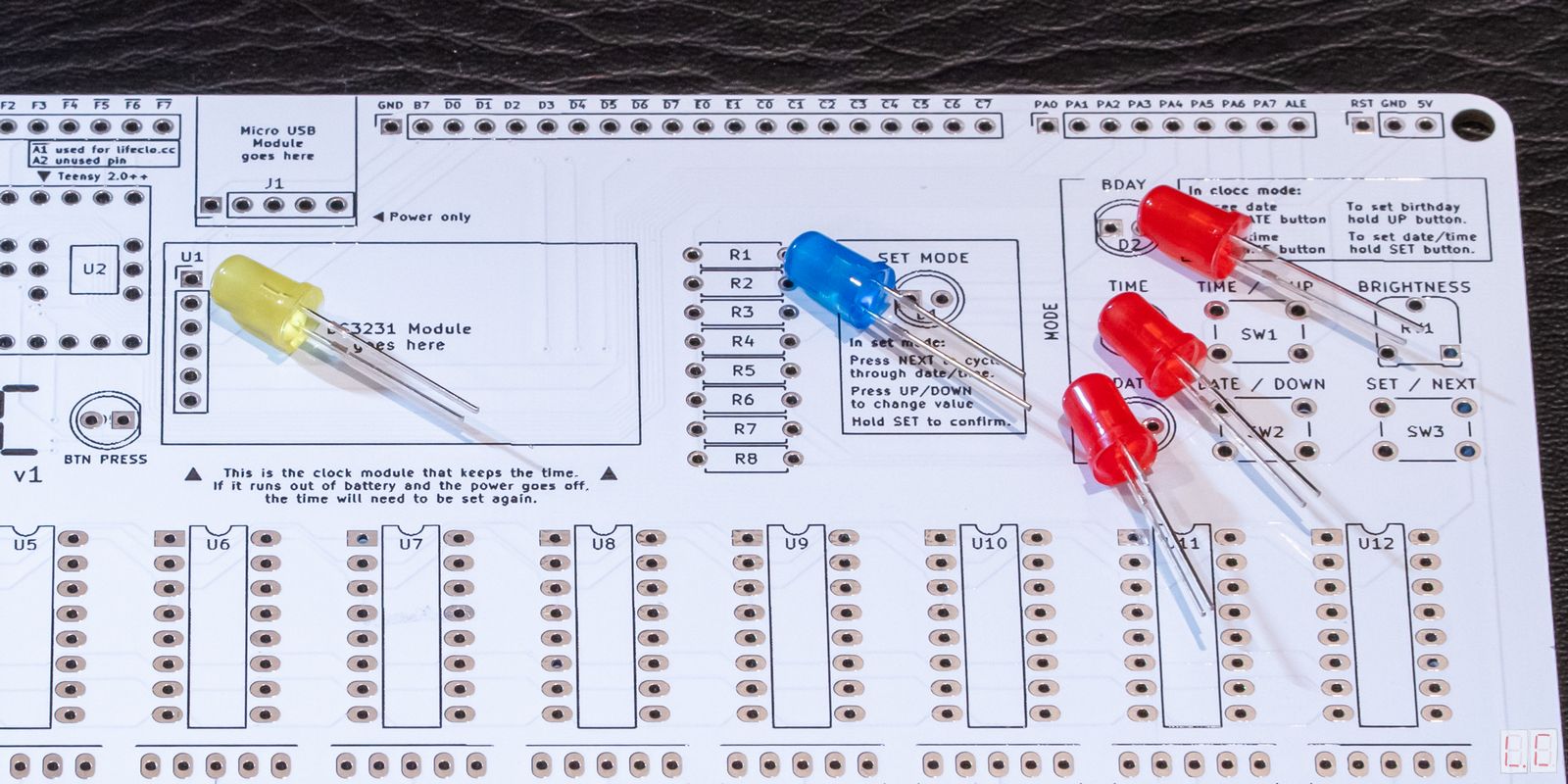
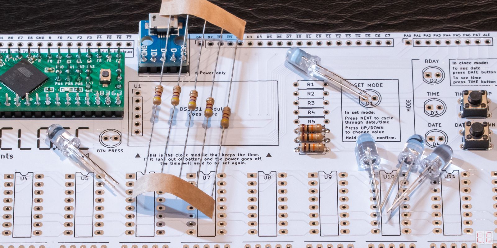
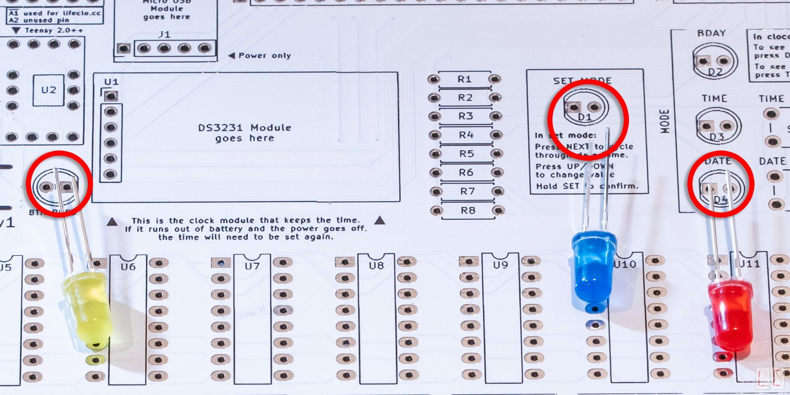
Solder three LEDs into D1
Solder one LEDs into D2, D3 and D4
Solder one LED into D5
The LEDs are directional. The shorter leg goes into the square hole.
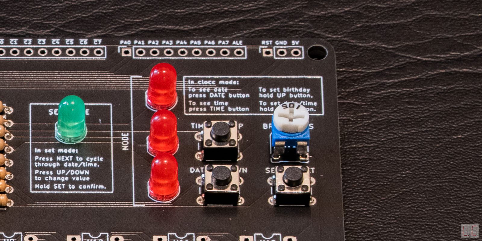
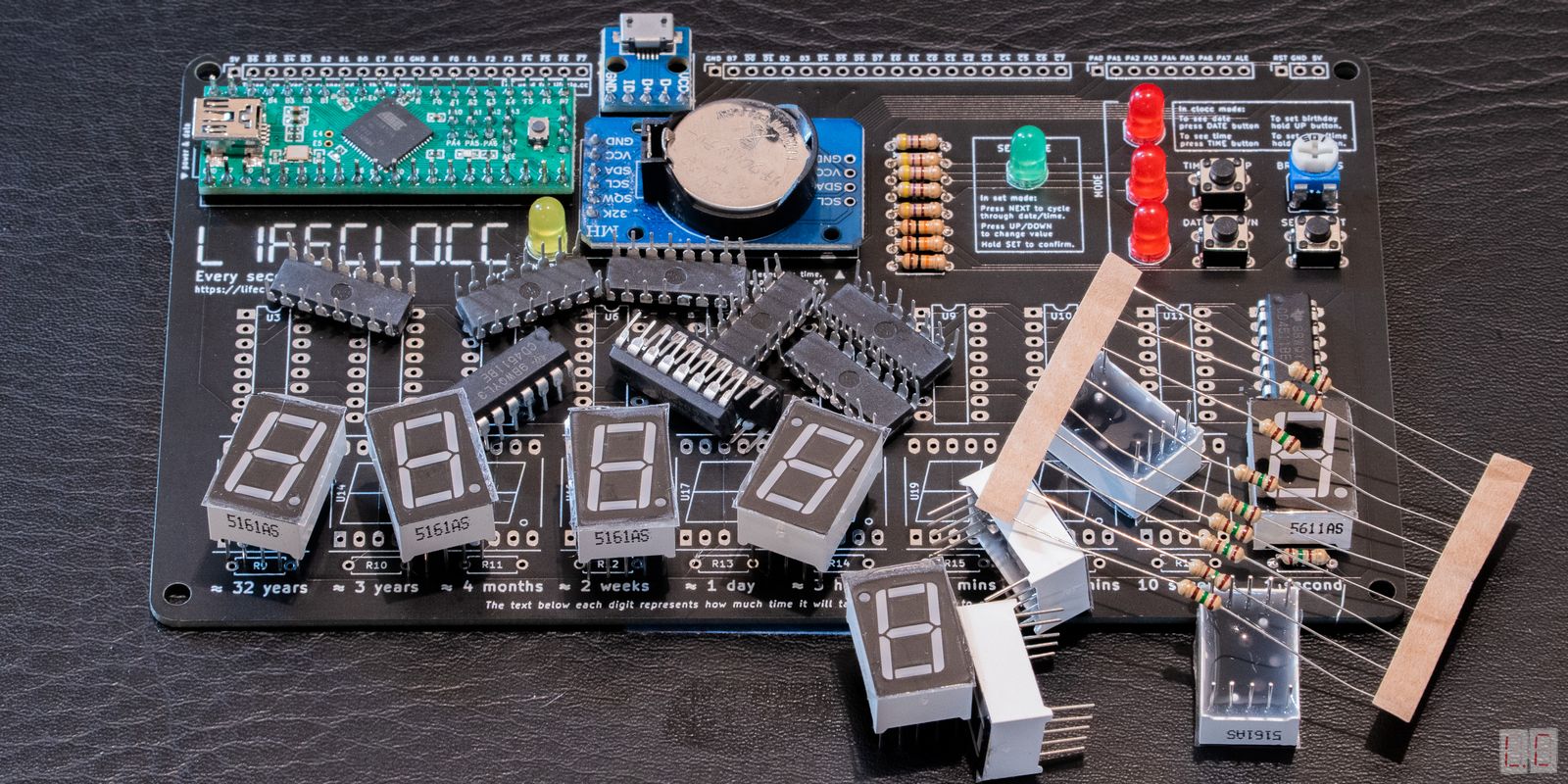
Required parts for this step. The resistor is the 470Ω one. The LEDs shown here are clear by mistake, but your package will have the colours. Colours may vary.
Plug the Teensy in.
All the LEDs should flash as it boots up. This will
indicate that it’s all working.
When you press the TIME and DATE buttons, the TIME and
DATE LEDs should light up.
When you press and hold the SET button, the SET MODE LED
should light up.
When you press and hold the TIME button, the BDAY and
SET MODE LED should light up.
Unplug the device before continuing.
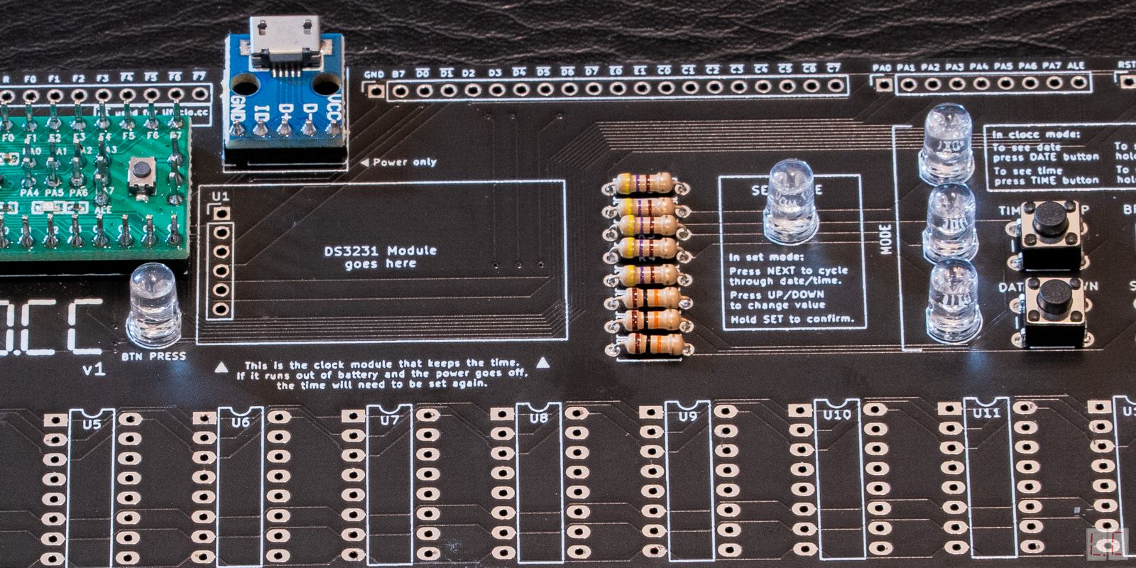
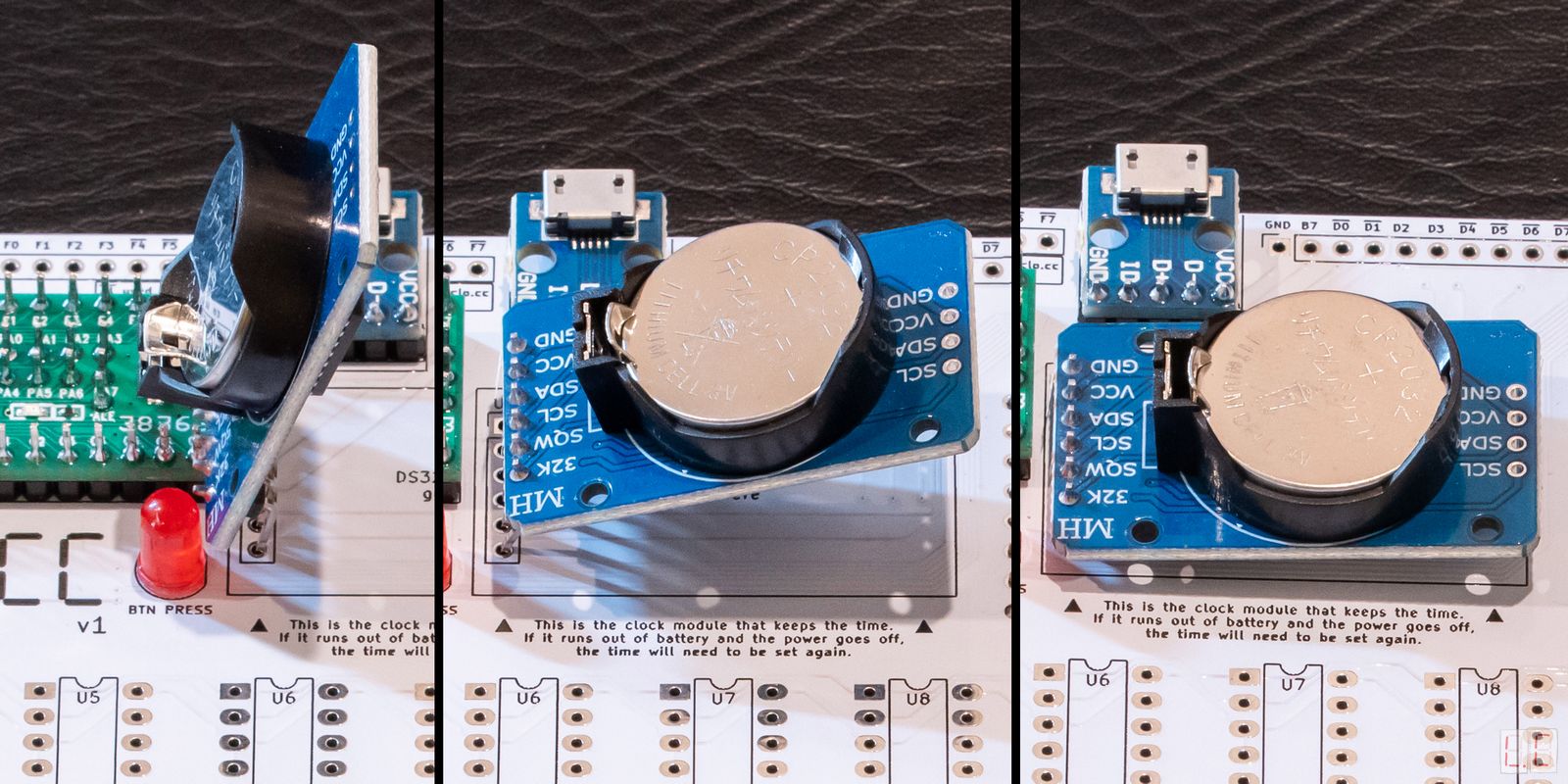
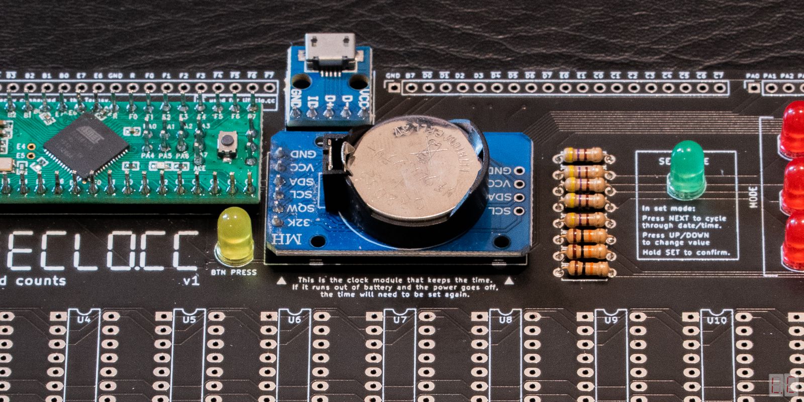
The clock module is the one with a battery. Remove the battery before installation. It comes with the pins bent at a right angle. You will need to bend the pins so that they are straight. Insert the module into the area labelled DS3231 Module goes here and solder it in.
Insert the battery after installation.
Plug the Teensy in
The clock module should have a red light indicating that
it's powered.
The only way to test if the clock is working is to
finish Step 7.
Solder the variable resistor and make sure you turn the dial all the way clockwise. This will ensure full brightness when you’re testing the displays.
No checkpoint here unfortunately.
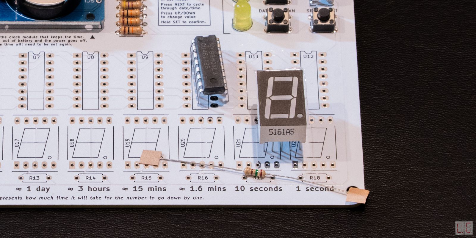
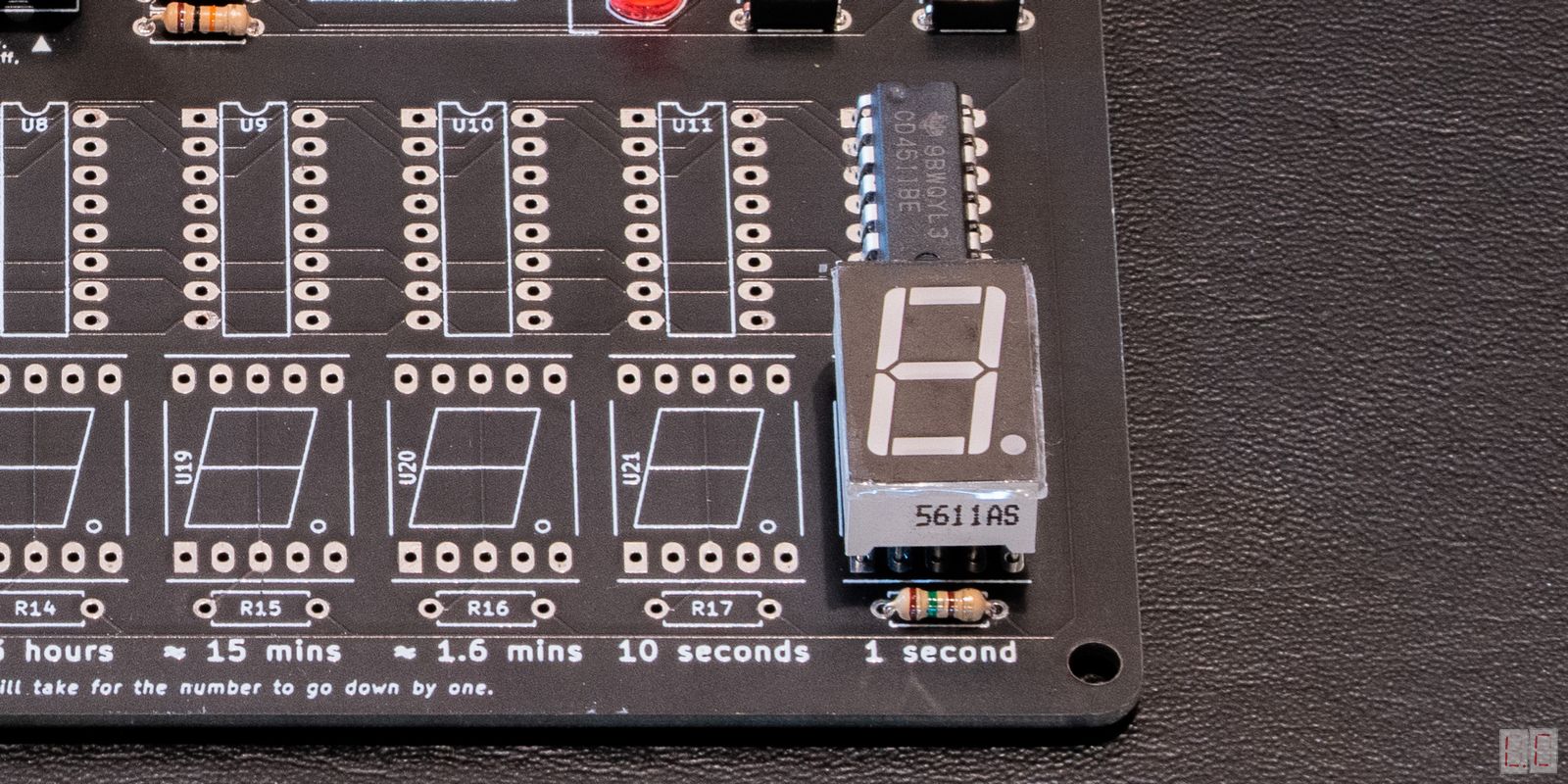
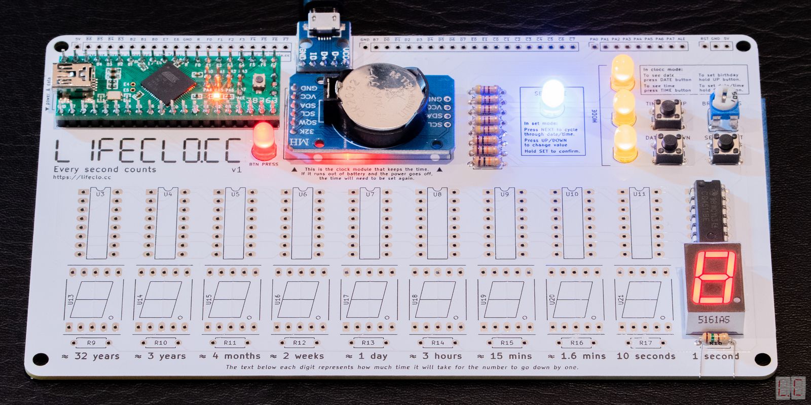
Solder the IC chip at U12. Make sure the small notch is facing up.
Solder the 7-segment display at U22. Make sure the decimal point is at the bottom.
Solder the resistor at R18. It doesn’t matter which way it is.
If you are using a green display, you will need a 22Ω Resistor. If you are using a red display, you will need a 150Ω Resistor.
Make sure that you put the IC and Display in the right
way up. Once soldered it's very hard to
fix.
The IC's notch should be facing up and the display's
decimal point should be at the bottom.
If you are still unsure,
please watch the video installation here.
Plug the Teensy in
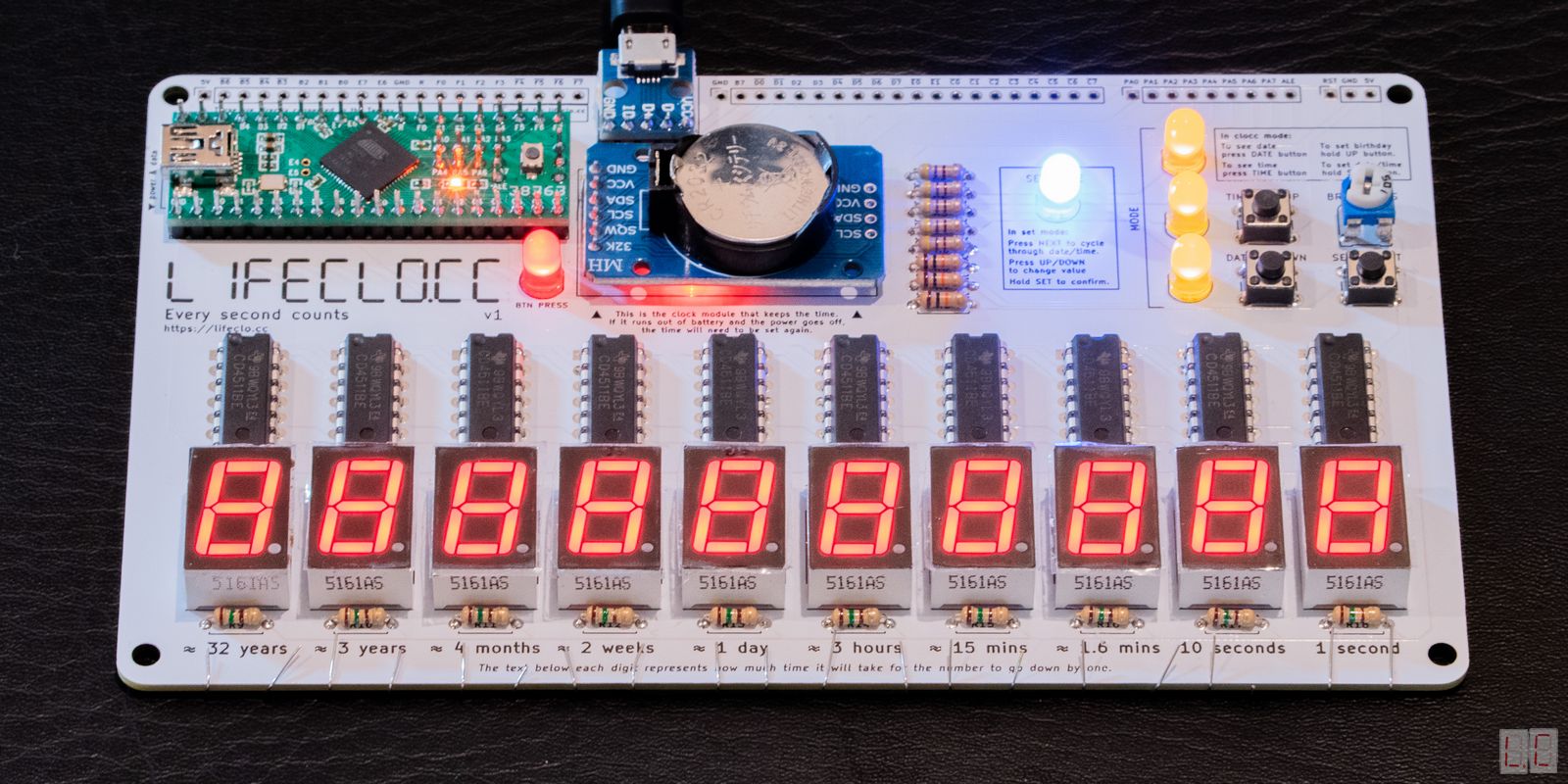
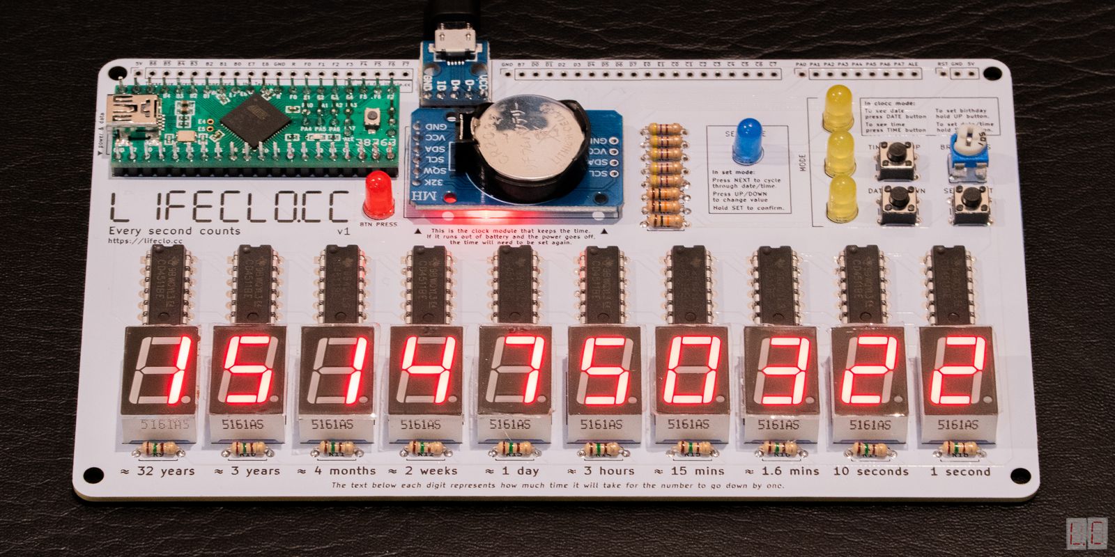
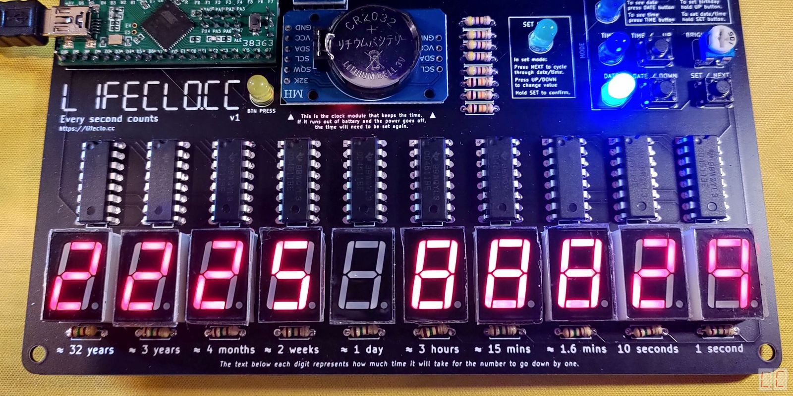
The first digit should show an 8 as the device boots up.
Then it should start counting down.
If this happens, that means the clock, and the Teensy
are both working!
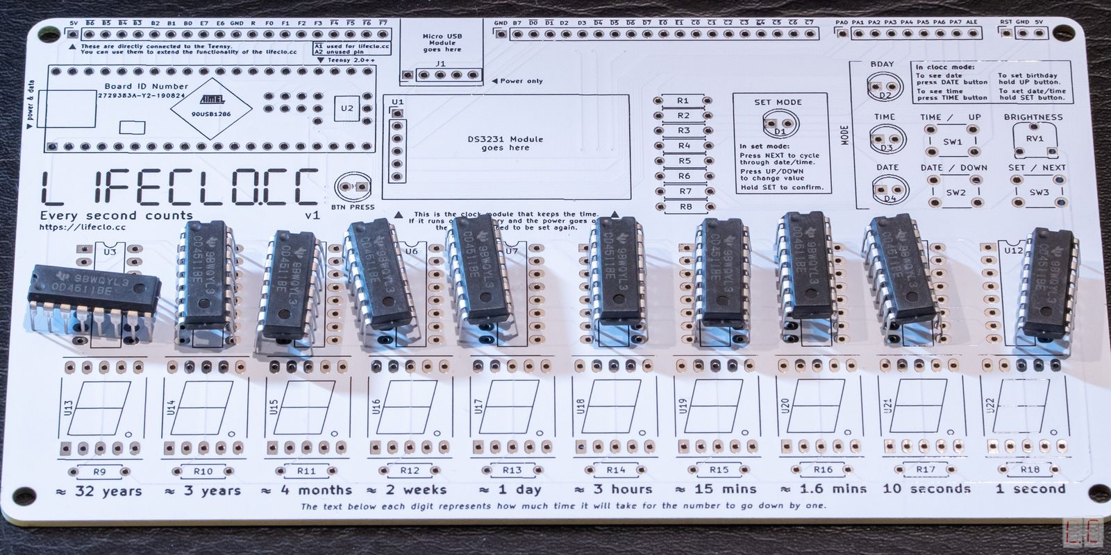
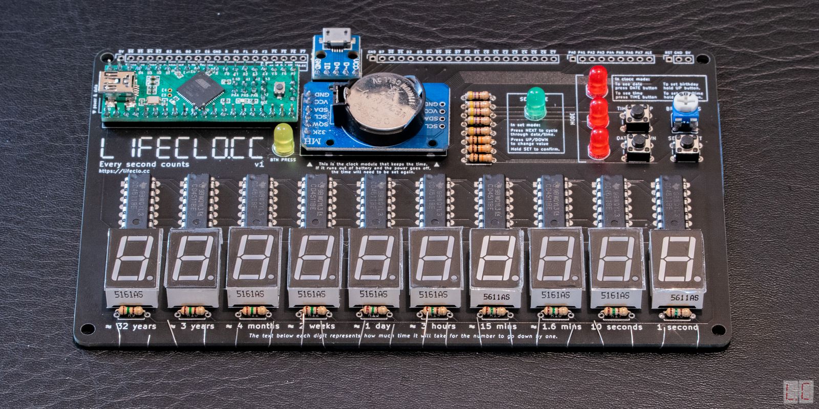
Repeat step 9 for the other digits. You can test each one after you install it. Please make sure you don't solder while the device is plugged in.
I've mentioned this in the previous section, but it
bears repeating
Make sure that you put the IC and Display in the right
way up. Once soldered it's very hard to
fix.
The IC's notch should be facing up and the display's
decimal point should be at the bottom.
If you are still unsure,
please watch the video installation here.
Plug the Teensy in
All the lights should blink to indicate that it's
working.
To enter debug mode, press and hold all 3 buttons for 3 seconds. This will cause all the lights to blink. This helps you determine if ther are any broken parts.
Turn the brightness dial to make sure it's working
Please refer to the operation manual to setup the date, time and birthday.
Unplug and plug it back in, the countdown should not have reset. (Make sure your button battery is in the clock module)
This board was made to be hackable. What that means is that the source code is open and you are free to do whatever you want to do with it.
In order to program this, you need to download the arduino IDE, and the Teensyduino plugin. You also need a mini USB B cable to program it.
The pins on the top of the board also act as a breakout to the Teensy, so you can attach other devices to the Teensy if you wish.